Arduino tutorial
Download Software & Install Driver
1. Windows System
(1) Download the Arduino IDE
When getting this control board, we need to install Arduino IDE
Enter the website
https://www.arduino.cc/,click and
and

Select the version you want to download, the latest version could be downloaded.

Alternatively, you could select previous release.
In this project, we use 1.8.12 version
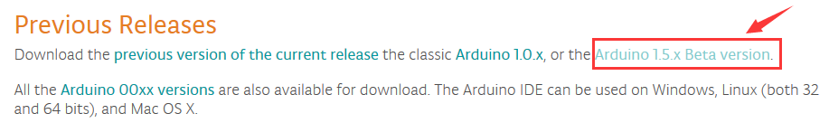
Click  to view the below page
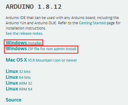
Click  to download an installer
of Arduino 1.8.12 version,which needs to be installed manually. When you
tap
to download an installer
of Arduino 1.8.12 version,which needs to be installed manually. When you
tap ,a zip file of Arduino 1.8.12
version will be directly downloaded, and you only need to unzip it to finish
installation.
,a zip file of Arduino 1.8.12
version will be directly downloaded, and you only need to unzip it to finish
installation.

Click icon to download Arduino
IDE.
to download Arduino
IDE.
(2) Download Driver of CH340
(3) Install the Driver
The driver will be installed after downloading Arduino IDE.
If your system is Windows 10, the computer will automatically install driver.
For other systems, like Windows7, we need to install driver manually.
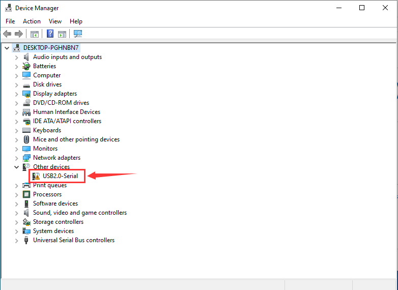
The USB to serial chip of control board is CH340G. Therefore, we will install the driver(usb_ch341_3.1.2009.06) for it.
Connect control board to computer with USB cable.
Click Computer—– Properties—– Device Manager, as shown below:
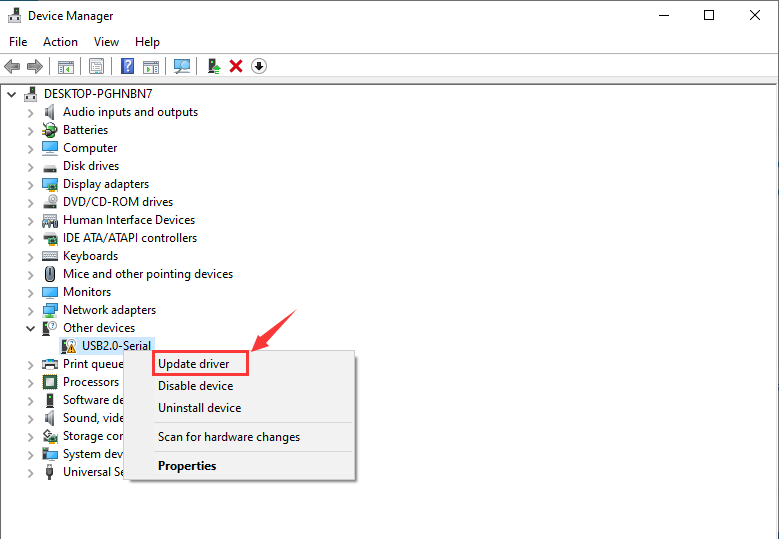
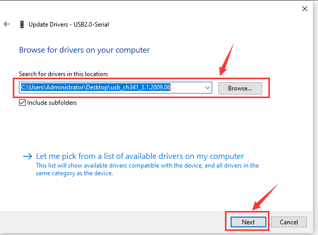
Then right-click on the USB2.0-Serial and select the top menu option (Update Driver) shown as the figure below.
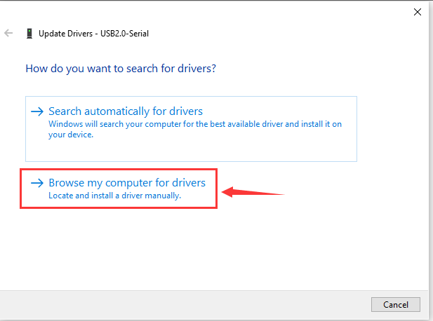
Then it will be prompted to either“Search automatically for driver ” or “Browse my computer for drivers”. Shown as below. In this page, select “Browse my computer for drivers”.
After that, select the option to browse and navigate to the “drivers” folder of usb_ch341_3.1.2009.06 installation.
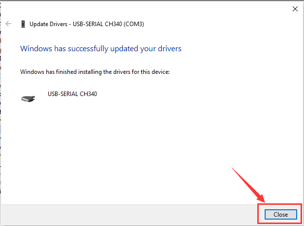
Once the software has been installed, you will get a confirmation message. Installation completed, click“Close”. http://wiki.keyestudio.com/index.php/File:Driver_6.png
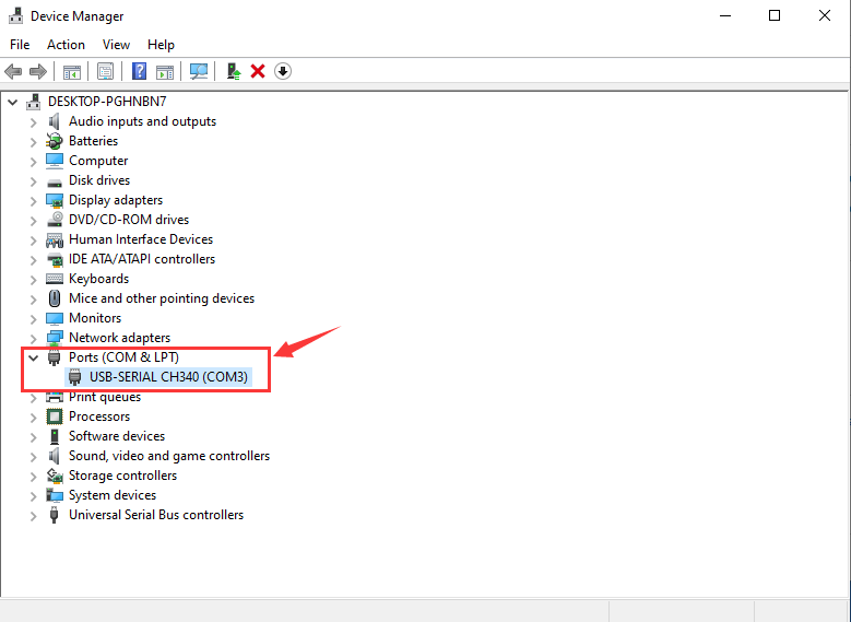
Now, the driver is installed well. Then you can right click
“Computer” —>“Properties”—>“Device manager”, you should see
the device as the figure shown below.
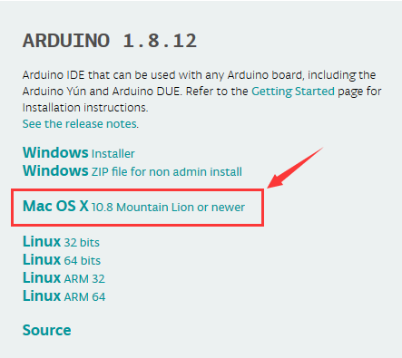
2. MAC System
(1) Install Arduino IDE on MAC System
The installation instruction is as same as chapter 3.1, as shown below:
(2) Download Driver of CH340
https://fs.keyestudio.com/CH340-MAC
(3) How to Install Driver of CH340
Please refer to the following link:
https://wiki.keyestudio.com/Download_CH340_Driver_on_MAC_System
There are various versions for Arduino, just download a suitable version for your system. We will take WINDOWS system as an example to show you how to download and install.
There are two versions for WINDOWS system, one is installed version, another one is download version. You just need to download the file to computer directly and unzip it. These two versions can be used normally. Choose one and download on your computer.
3. Arduino IDE Setting
Click icon,open Arduino IDE.
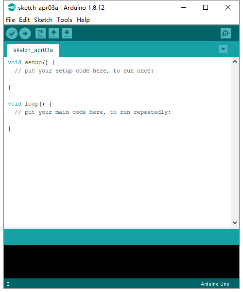
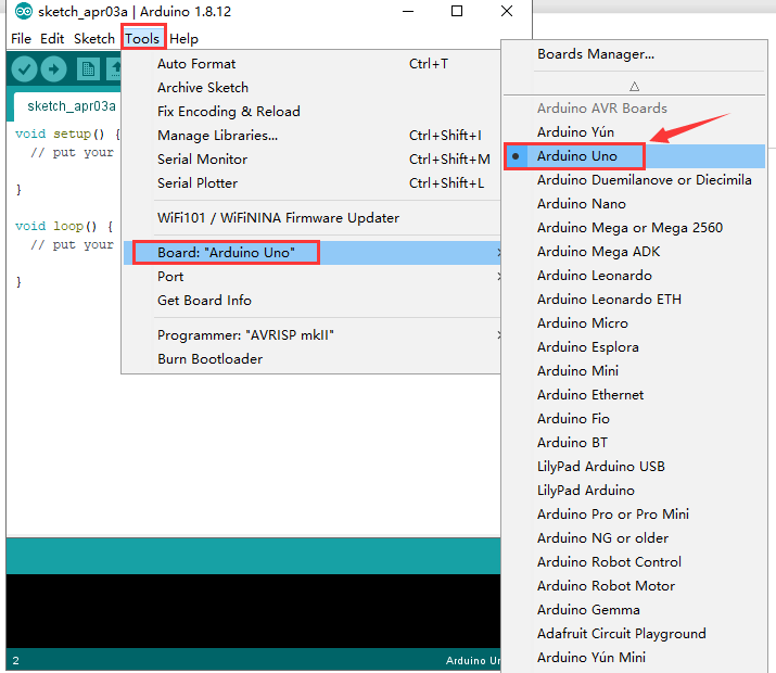
To avoid the errors when uploading the program to the board, you need to select the correct Arduino board that matches the board connected to your computer.
Then come back to the Arduino software, you should click Tools→Board, select the board. (as shown below)
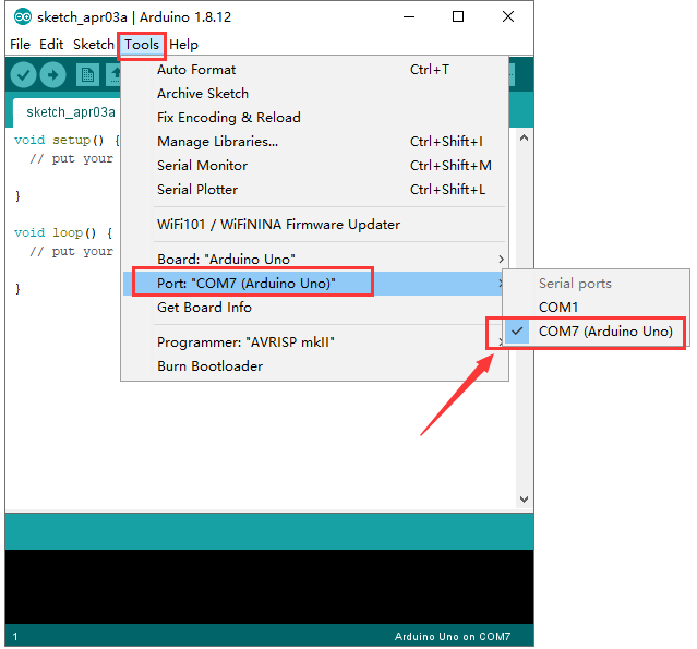
Then select the correct COM port (you can see the corresponding COM port after the driver is successfully installed)
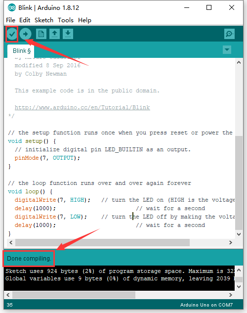
Before uploading the program to the board, let’s demonstrate the function of each symbol in the Arduino IDE toolbar.
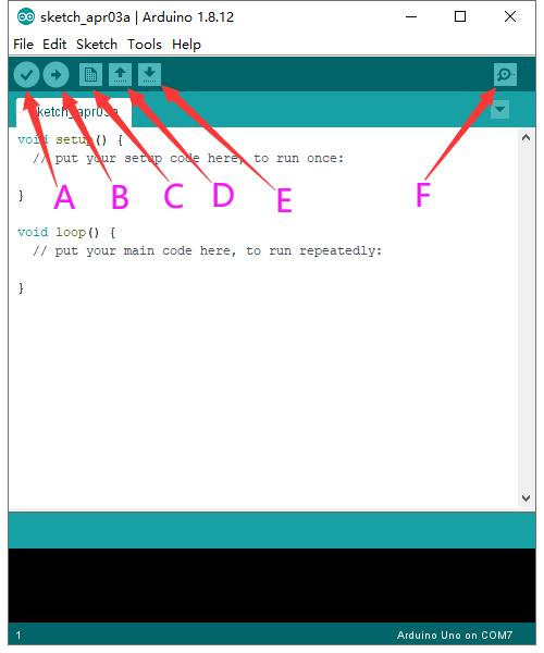
A- Used to verify whether there is any compiling mistakes or not.
B- Used to upload the sketch to your Arduino board.
C- Used to create shortcut window of a new sketch.
D- Used to directly open an example sketch.
E- Used to save the sketch.
F- Used to send the serial data received from board to the serial monitor.
4. Start your first program
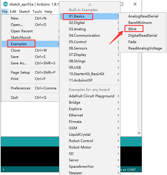
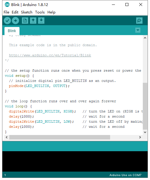
Open the file to select Example, choose BLINK from BASIC, as shown below:
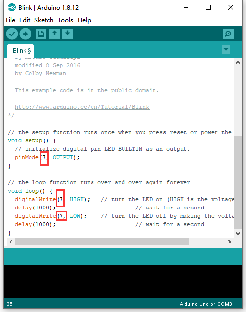
dfInterface D3, D5, D6, D7, D8 in the coding box all can control LEDs. During the test, it is necessary to change the code in LED_BUILTIN to the corresponding interface. For example, in the picture below, it is D7.
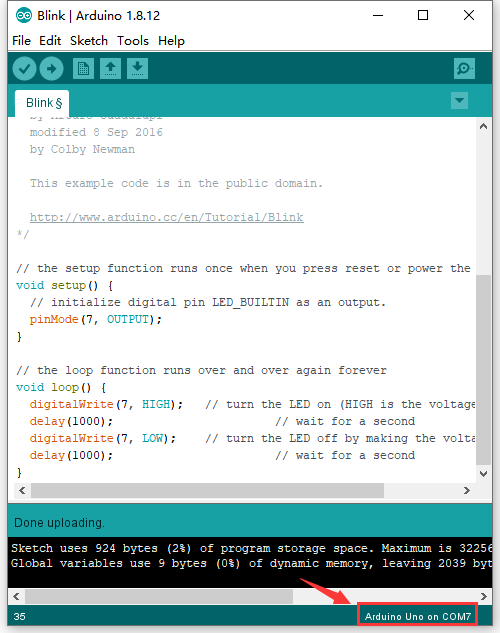
Set board and COM port, the corresponding board and COM port are shown on the lower right of IDE.
Click to start compiling the
program, and check errors.
to start compiling the
program, and check errors.
Click to upload the program,
upload successfully.
to upload the program,
upload successfully.
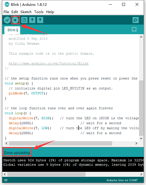
Upload the program successfully, the on-board LED lights on for 1s, lights off for 1s. Congratulation, you have finished the first program.
5. Add Libraries to Arduino
What are Libraries ?
Libraries are a collection of code that makes it easy for you to connect to a sensor, display, module, etc.
For example, the built-in LiquidCrystal library helps LCD displays.
There are hundreds of additional libraries available on the Internet for download.
Here we will introduce the most simple way for you to add libraries .
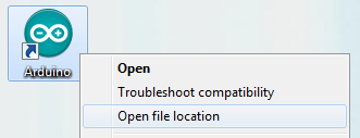
Step 1:After downloading well the Arduino IDE, you can right-click the icon of Arduino IDE.
Find the option “Open file location” shown as below:
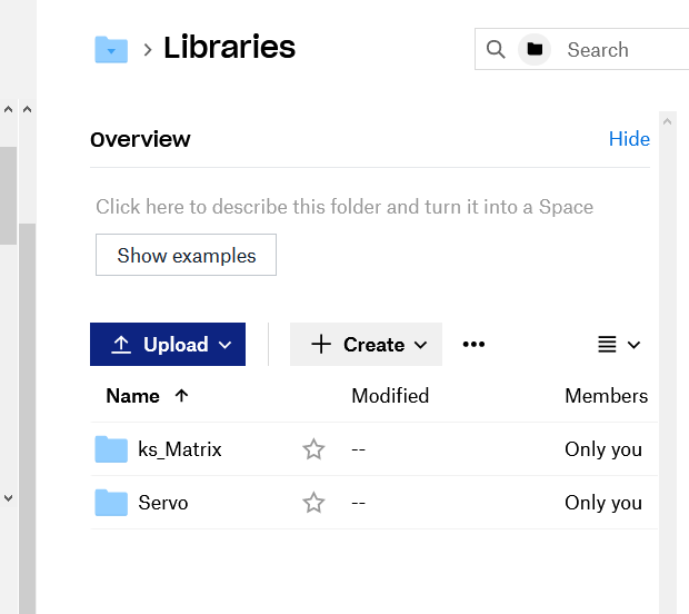
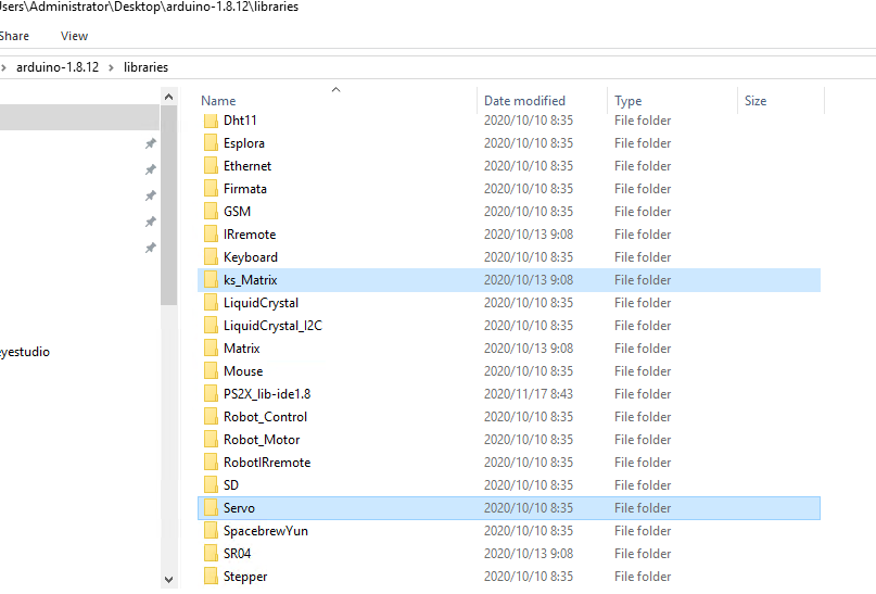
Step 2: Enter it to find libraries folder which is the library file of Arduino.
Step 3:Next to find out the“libraries”of coding box kit(seen in the link:
You just need to replicate and paste its libraries into the libraries of Arduino IDE.
The library of this kit is successfully installed, as shown below:
Projects
Project 1: Hello World

Project Introduction
As for starters, we will begin with something simple. In this project, you only need a PLUS board and a USB cable to start the “Hello World!” project. It is not only a communication test of your Arduino and PC, but also an enlightening project for you to have your first try in the Arduino world!
Project Code
After installing driver for Arduino, let’s open Arduino software and compile code that enables Arduino to print “Hello World!” .
  \*Kidsbits Coding Box

  Project 1

  Hello World

  http//www.kidsbits.cc

  */

  int val;//define variable val

  void setup()

  {

  Serial.begin(9600);// set the baud rate at 9600 .

  }

  void loop()

  {

  val=Serial.read();// read the Introduction or character from PC to Arduino, and
  assign them to Val.

  if(val=='R')// determine if the Introduction or character received is “R”.

  { // if it’s “R”,

  Serial.println("Hello World!");// display“Hello World!”string.

  }}

  /////////////////////////////////////////////////////////////////
Project Result
Click to open the serial monitor, input an“R”, PC will receive the information from Arduino Hello World!
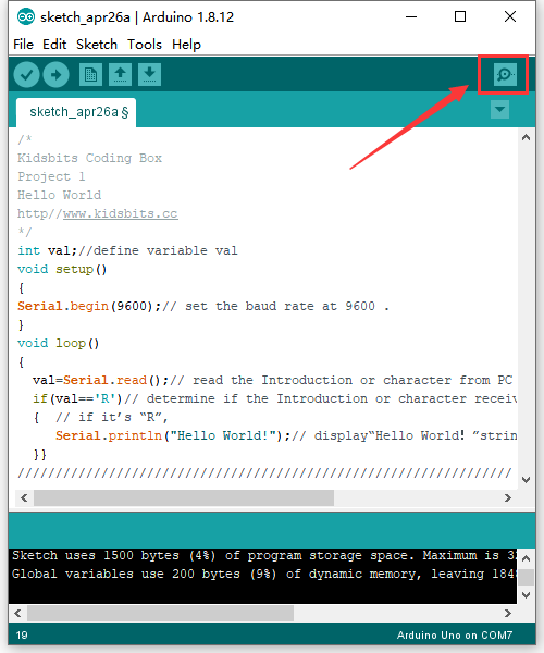
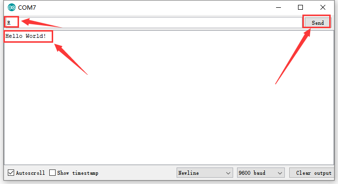
After choosing the proper port, the project is easy for you!
next project***
Project 2: Blink
Project Introduction
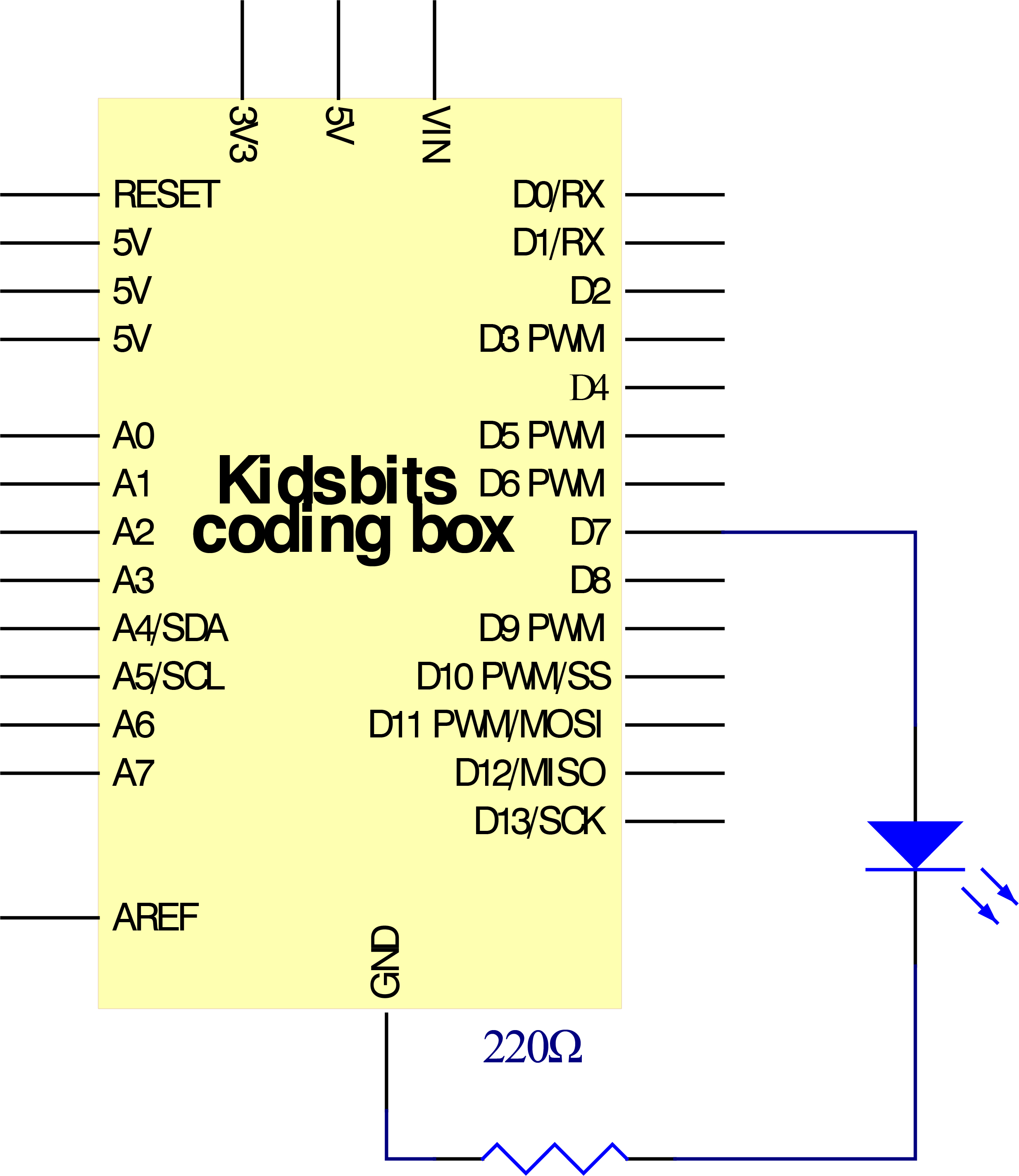
In this project, we start to learn the digital output of Arduino. We used the digital pin of Arduino to turn on an LED and let it blink.
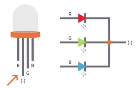
Working Principle
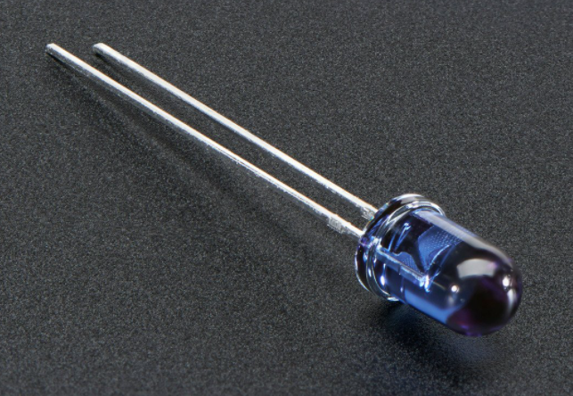
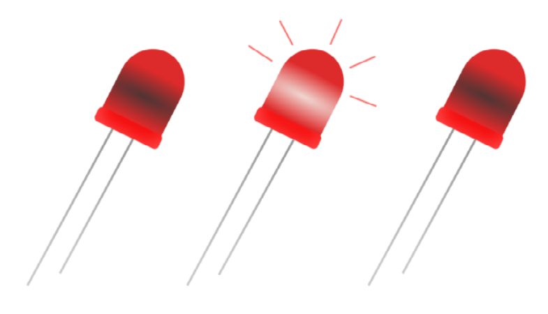
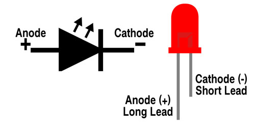
LED is a type of semiconductor called “Light Emitting Diode “which is an
electronic device made of semiconductor materials (silicon, selenium, germanium,
etc.). It is dubbed indicator, digital and word display in circuit and device.
It has positive and negative poles. The short leg is the negative pole, and the
long one is the positive pole.
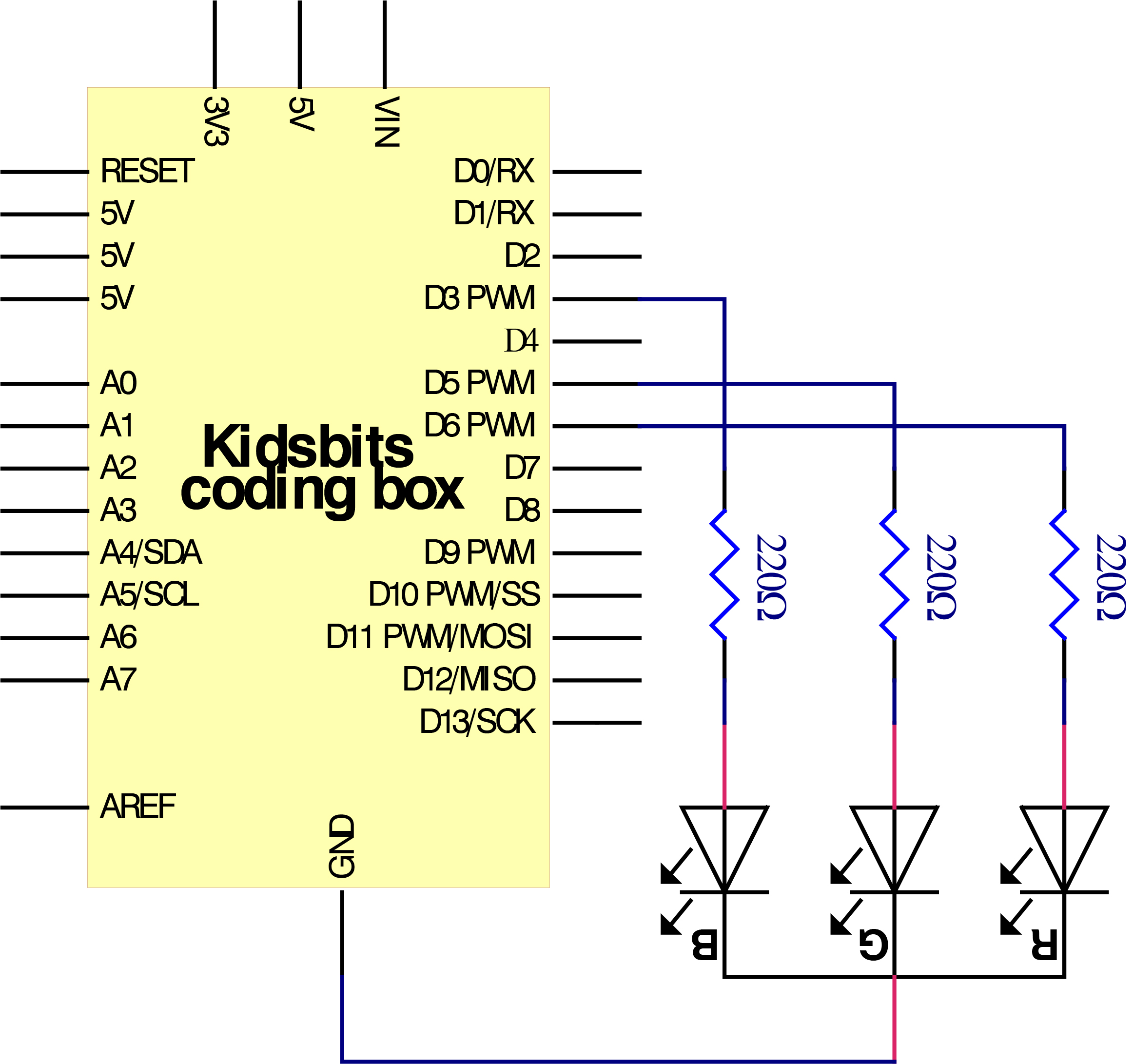
Circuit Connection
Project Code
  \*Kidsbits Coding Box

  Project 2

  Blink

  http//www.kidsbits.cc

  */

  int ledPin = 7; // define digital pin 7.

  void setup()

  {

  pinMode(ledPin, OUTPUT);// define led pin as output.

  }

  void loop()

  {

  digitalWrite(ledPin, HIGH); // set the LED on.

  delay(1000); // wait for a second.

  digitalWrite(ledPin, LOW); // set the LED off.

  delay(1000); // wait for a second

  }

  //////////////////////////////////////////////////////////////////
Project Result
Upload the code to the coding box successfully, you can see that the red LED of D7 starts blinking, which is on for 1 second and off for 1 second.
next project***
Project 3: SOS

Project Introduction
The SOS distress signal is an international Morse code distress signal asking for help. Morse code is a character encoding. Each letter of English is composed of different combinations of bars and dots. The advantage of this is that using the simple two symbols all letters and numbers can be transmitted, which is very simple!
Working Principle
The letters can be spelled out through the two states of the LED switch, using long flashing and short flashing to indicate dots and bars. Just spell the three letters S.O.S.
By consulting the Morse code table, we can know that the letter “S” is represented by three dots, and we use short blinking instead, and the letter “O” is represented by three horizontal bars, which is replaced by long blinking here.
Circuit Connection
Project Code
  \*Kidsbits Coding Box

  Project 3

  s o s

  http//www.kidsbits.cc

  */

  int ledPin = 7;

  void setup()

  {

  pinMode(ledPin, OUTPUT);

  }

  void loop() {

  // Three fast flashes to indicate the letter "S"

  for(int x=0;x\<3;x++){

  digitalWrite(ledPin,HIGH); //Set the LED to on

  delay(150); //Delay 150 milliseconds

  digitalWrite(ledPin,LOW); //Set the LED to off

  delay(100); //Delay 100 milliseconds

  }

  delay(100);

  //Three short flashes to indicate the letter "O"

  for(int x=0;x\<3;x++)

  {

  digitalWrite(ledPin,HIGH); //Set the LED to on

  delay(400); //delay 400 milliseconds

  digitalWrite(ledPin,LOW); //Set the LED to off

  delay(100); //delay 100 milliseconds

  }

  delay(100);

  // three quick flashes to represent the letter "S"

  for(int x=0;x\<3;x++)

  {

  digitalWrite(ledPin,HIGH); //Set the LED to on

  delay(150); //Delay 150 milliseconds

  digitalWrite(ledPin,LOW); //Set the LED to off

  delay(100); //delay 100 milliseconds

  }

  // Wait 5 seconds before repeating the S.0.S signal

  delay(5000);

  }

  \\\\\\\\\\\\\\\\\\\\\\\\\\\\\\\\\\\\\\\\\\\\\\\\\\\\\\\\\\\\\\\\\\
Project Result
After uploading the code to the coding box, you can see that the red LED at D7 fast flash 3 times and then slowly flash 3 times alternatively, which can stimulate SOS alarm in Morse code.
next project***
Project 4: PWM
Project Introduction
In this project, we will learn the PWM control of ARDUINO. PWM is the abbreviation of Pulse Width Modulation, which is a technology that encodes analog signal level into digital signal level. We use PWM to control an LED gradually from bright to dark.
Working Principle

The PWM signal is also digitalized because in any given moment, fully on DC power supply is either 5V (ON), or 0V (OFF). The voltage or current is fed to the analog load (the device that uses the power) by repeated pulse sequence being ON or OFF. Being on, the current is fed to the load; being off, it’s not. With adequate bandwidth, any analog value can be encoded using PWM. The output voltage value is calculated via the on and off time.
Output voltage = (turn on time/pulse time) maximum voltage value
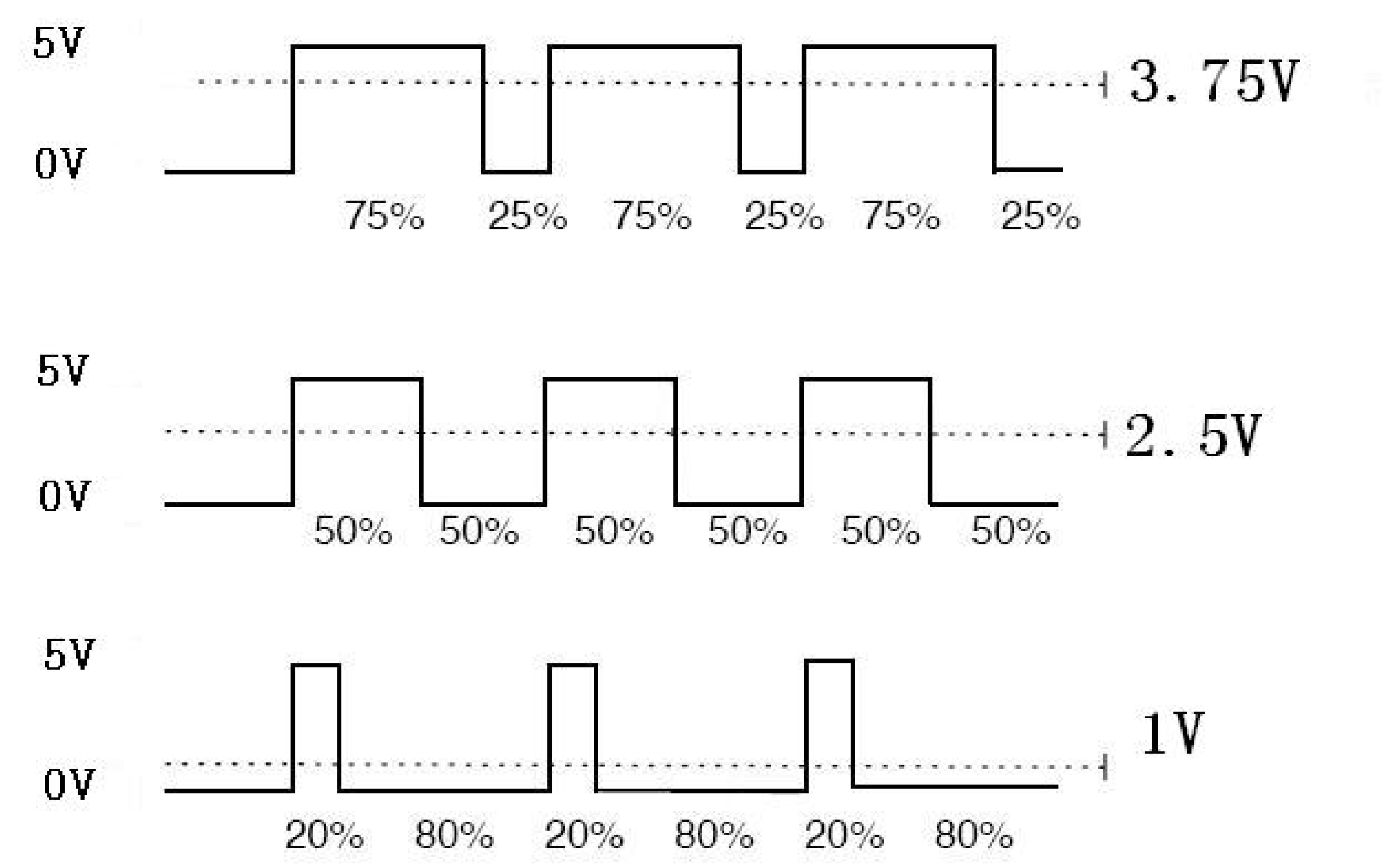
PWM has many applications like lamp brightness regulating, motor speed regulating, sound making, etc.
The following are the three basic parameters of PMW.
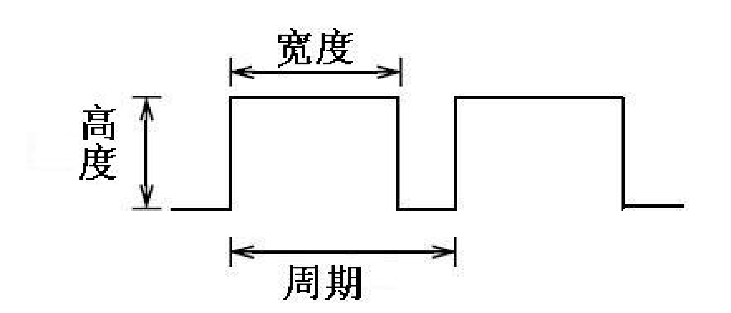
The amplitude of pulse width (minimum / maximum)
2. The pulse period (The reciprocal of pulse frequency in one second)
3. The voltage level(such as 0V-5V)
There are 6 PMW interfaces on Arduino, namely digital pin 3, 5, 6, 9, 10, and 11.
In previous experiments, we have done “button-controlled LED”, using digital signal to control digital pin, also one about potentiometer.
This time, we will use a potentiometer to control the brightness of the LED.
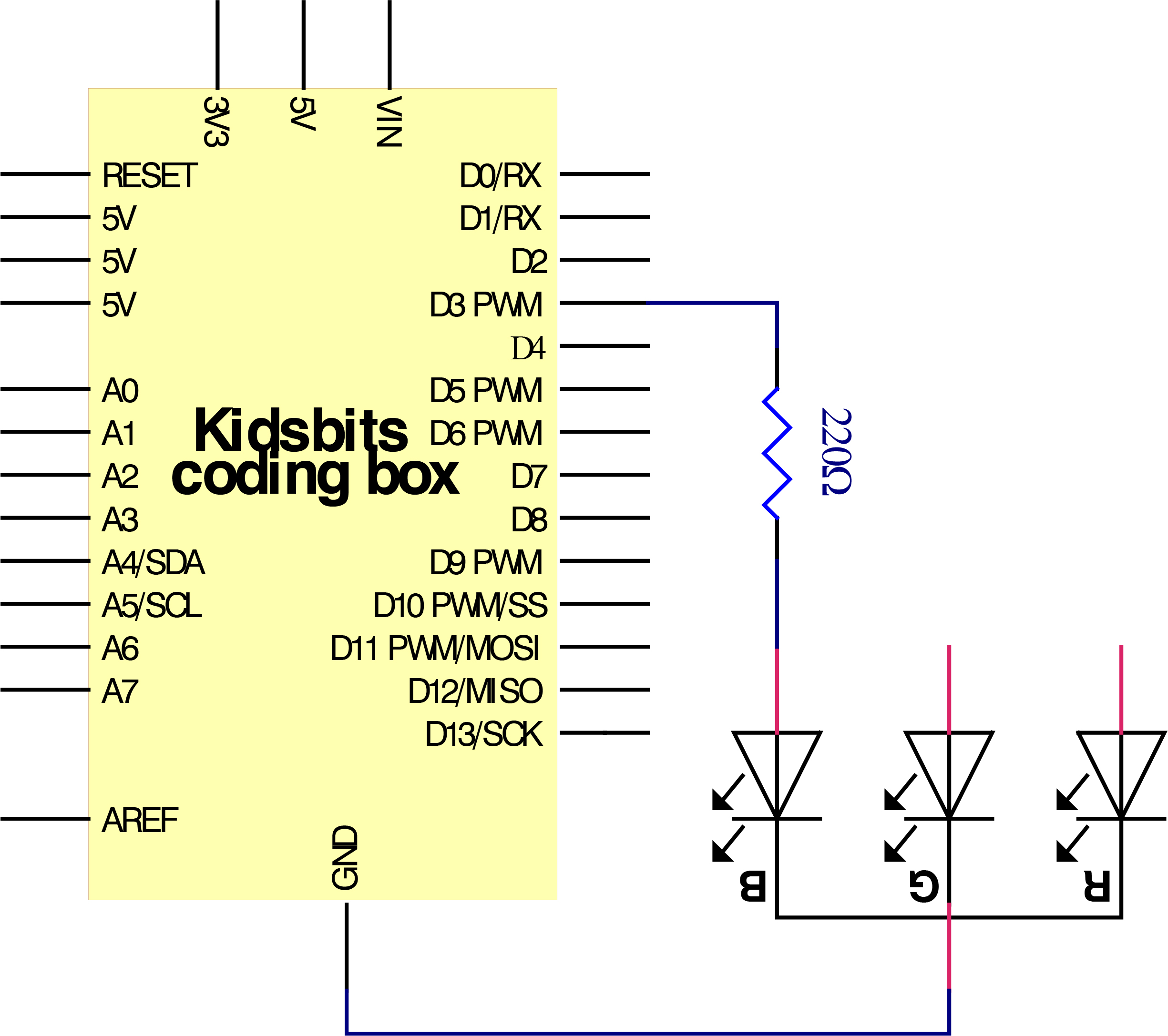
Circuit Connection
Project Code
  \*Kidsbits Coding Box

  Project 4

  PWM

  http//www.kidsbits.cc

  */

  int ledPin = 3;

  void setup()

  {

  pinMode(ledPin,OUTPUT);

  }

  void loop(){

  for (int value = 0 ; value \< 255; value=value+1){

  analogWrite(ledPin, value);

  delay(5);

  }

  for (int value = 255; value \>0; value=value-1){

  analogWrite(ledPin, value);

  delay(5);

  } }

  /////////////////////////////////////////////////////////////////
Project Result
After uploading the code to the coding box, you can see the blue light in the RGB on the coding box constantly brightening and dimming, just like a breathing light.
next project***
Project 5: RGB Color
Project Introduction
The RGB color mode is a color standard in the industry. It obtains various colors by changing the three color channels of red (R), green (G), and blue (B) and integrating them. RGB denotes the three colors of red, green and blue.
Working Principle
The monitors mostly adopt the RGB color standard, and all the colors on the computer screen are composed of the three colors of red, green and blue mixed in different proportions.
And we could adjust the LED brightness by PWM.
Circuit Connection
Project Result
After uploading the code to the coding box, you can see the light of the RGB light on the coding box, and the color keeps changing.
next project***
Project 6: Play Music
Project Introduction

In the previous project, we studied the active buzzer, which can only emit one sound, which feels rather monotonous.
This project will learn another buzzer, passive buzzer. The characteristic of the passive buzzer is that it can emit sounds of different frequencies. This characteristic allows the buzzer to play music melody.
We used the shape of a bird that really likes to sing to complete this project. We can code some different songs, which is very interesting.
Working Principle
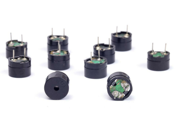
Passive buzzer is an integrated electronic buzzer without vibration source inside. It must be driven by 2K-5K square wave instead of direct current signals. There is little difference between the two kinds of buzzers, but when the pins of the two buzzers are placed up, the passive buzzer comes with green circuit board, and the one sealed with vinyl is an active buzzer.
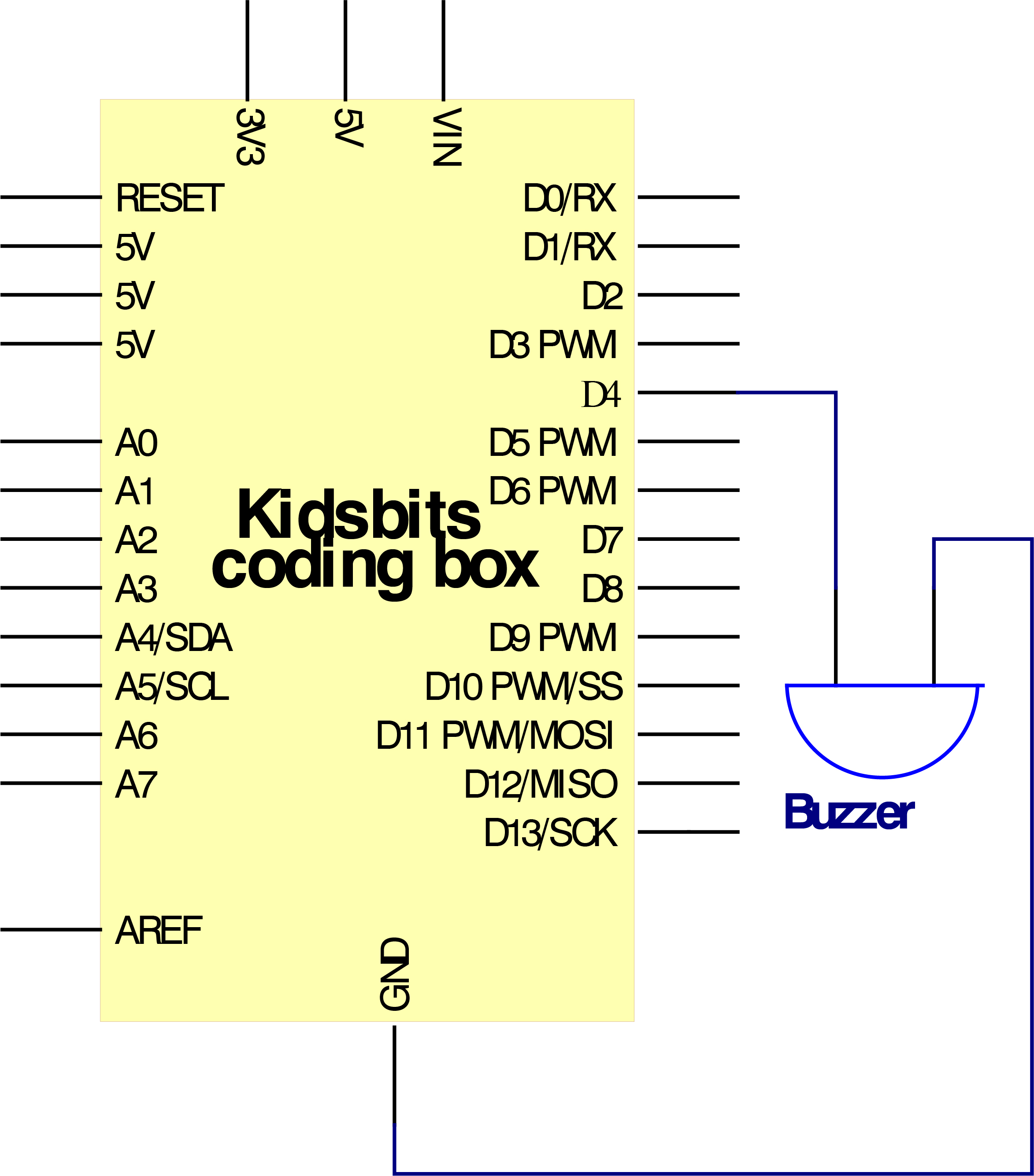
Circuit Connection
Project Code
  \*Kidsbits Coding Box

  Project 6

  Play Music

  http//www.kidsbits.cc

  */

  \#define NOTE_B0 31

  \#define NOTE_C1 33

  \#define NOTE_CS1 35

  \#define NOTE_D1 37

  \#define NOTE_DS1 39

  \#define NOTE_E1 41

  \#define NOTE_F1 44

  \#define NOTE_FS1 46

  \#define NOTE_G1 49

  \#define NOTE_GS1 52

  \#define NOTE_A1 55

  \#define NOTE_AS1 58

  \#define NOTE_B1 62

  \#define NOTE_C2 65

  \#define NOTE_CS2 69

  \#define NOTE_D2 73

  \#define NOTE_DS2 78

  \#define NOTE_E2 82

  \#define NOTE_F2 87

  \#define NOTE_FS2 93

  \#define NOTE_G2 98

  \#define NOTE_GS2 104

  \#define NOTE_A2 110

  \#define NOTE_AS2 117

  \#define NOTE_B2 123

  \#define NOTE_C3 131

  \#define NOTE_CS3 139

  \#define NOTE_D3 147

  \#define NOTE_DS3 156

  \#define NOTE_E3 165

  \#define NOTE_F3 175

  \#define NOTE_FS3 185

  \#define NOTE_G3 196

  \#define NOTE_GS3 208

  \#define NOTE_A3 220

  \#define NOTE_AS3 233

  \#define NOTE_B3 247

  \#define NOTE_C4 262

  \#define NOTE_CS4 277

  \#define NOTE_D4 294

  \#define NOTE_DS4 311

  \#define NOTE_E4 330

  \#define NOTE_F4 349

  \#define NOTE_FS4 370

  \#define NOTE_G4 392

  \#define NOTE_GS4 415

  \#define NOTE_A4 440

  \#define NOTE_AS4 466

  \#define NOTE_B4 494

  \#define NOTE_C5 523

  \#define NOTE_CS5 554

  \#define NOTE_D5 587

  \#define NOTE_DS5 622

  \#define NOTE_E5 659

  \#define NOTE_F5 698

  \#define NOTE_FS5 740

  \#define NOTE_G5 784

  \#define NOTE_GS5 831

  \#define NOTE_A5 880

  \#define NOTE_AS5 932

  \#define NOTE_B5 988

  \#define NOTE_C6 1047

  \#define NOTE_CS6 1109

  \#define NOTE_D6 1175

  \#define NOTE_DS6 1245

  \#define NOTE_E6 1319

  \#define NOTE_F6 1397

  \#define NOTE_FS6 1480

  \#define NOTE_G6 1568

  \#define NOTE_GS6 1661

  \#define NOTE_A6 1760

  \#define NOTE_AS6 1865

  \#define NOTE_B6 1976

  \#define NOTE_C7 2093

  \#define NOTE_CS7 2217

  \#define NOTE_D7 2349

  \#define NOTE_DS7 2489

  \#define NOTE_E7 2637

  \#define NOTE_F7 2794

  \#define NOTE_FS7 2960

  \#define NOTE_G7 3136

  \#define NOTE_GS7 3322

  \#define NOTE_A7 3520

  \#define NOTE_AS7 3729

  \#define NOTE_B7 3951

  \#define NOTE_C8 4186

  \#define NOTE_CS8 4435

  \#define NOTE_D8 4699

  \#define NOTE_DS8 4978

  \#define REST 0

  // change this to make the song slower or faster

  int tempo=114;

  // change this to whichever pin you want to use

  int buzzer = 4;

  // notes of the moledy followed by the duration.

  // a 4 means a quarter note, 8 an eighteenth , 16 sixteenth, so on

  // !!negative numbers are used to represent dotted notes,

  // so -4 means a dotted quarter note, that is, a quarter plus an eighteenth!!

  int melody[] = {

  NOTE_E4,4, NOTE_E4,4, NOTE_F4,4, NOTE_G4,4,//1

  NOTE_G4,4, NOTE_F4,4, NOTE_E4,4, NOTE_D4,4,

  NOTE_C4,4, NOTE_C4,4, NOTE_D4,4, NOTE_E4,4,

  NOTE_E4,-4, NOTE_D4,8, NOTE_D4,2,

  NOTE_E4,4, NOTE_E4,4, NOTE_F4,4, NOTE_G4,4,//4

  NOTE_G4,4, NOTE_F4,4, NOTE_E4,4, NOTE_D4,4,

  NOTE_C4,4, NOTE_C4,4, NOTE_D4,4, NOTE_E4,4,

  NOTE_D4,-4, NOTE_C4,8, NOTE_C4,2,

  NOTE_D4,4, NOTE_D4,4, NOTE_E4,4, NOTE_C4,4,//8

  NOTE_D4,4, NOTE_E4,8, NOTE_F4,8, NOTE_E4,4, NOTE_C4,4,

  NOTE_D4,4, NOTE_E4,8, NOTE_F4,8, NOTE_E4,4, NOTE_D4,4,

  NOTE_C4,4, NOTE_D4,4, NOTE_G3,2,

  NOTE_E4,4, NOTE_E4,4, NOTE_F4,4, NOTE_G4,4,//12

  NOTE_G4,4, NOTE_F4,4, NOTE_E4,4, NOTE_D4,4,

  NOTE_C4,4, NOTE_C4,4, NOTE_D4,4, NOTE_E4,4,

  NOTE_D4,-4, NOTE_C4,8, NOTE_C4,2

  };

  // sizeof gives the number of bytes, each int value is composed of two bytes (16
  bits)

  // there are two values per note (pitch and duration), so for each note there
  are four bytes

  int notes=sizeof(melody)/sizeof(melody[0])/2;

  // this calculates the duration of a whole note in ms (60s/tempo)4 beats

  int wholenote = (60000 4) / tempo;

  int divider = 0, noteDuration = 0;

  void setup() {

  // iterate over the notes of the melody.

  // Remember, the array is twice the number of notes (notes + durations)

  for (int thisNote = 0; thisNote \< notes 2; thisNote = thisNote + 2) {

  // calculates the duration of each note

  divider = melody[thisNote + 1];

  if (divider \> 0) {

  // regular note, just proceed

  noteDuration = (wholenote) / divider;

  } else if (divider \< 0) {

  // dotted notes are represented with negative durations!!

  noteDuration = (wholenote) / abs(divider);

  noteDuration = 1.5; // increases the duration in half for dotted notes

  }

  // we only play the note for 90% of the duration, leaving 10% as a pause

  tone(buzzer, melody[thisNote], noteDuration0.9);

  // Wait for the specief duration before playing the next note.

  delay(noteDuration);

  // stop the waveform generation before the next note.

  noTone(buzzer);

  }

  }

  void loop() {

  // if you want to repeat the song forever,

  // just paste the setup code here instead.

  }

  /////////////////////////////////////////////////////////////////
Project Result
After uploading the code to the coding box, you can hear the buzzer playing the song “Ode to Joy” on the coding box.
next project***
Project 7: Small Desktop Lamp

Project Introduction
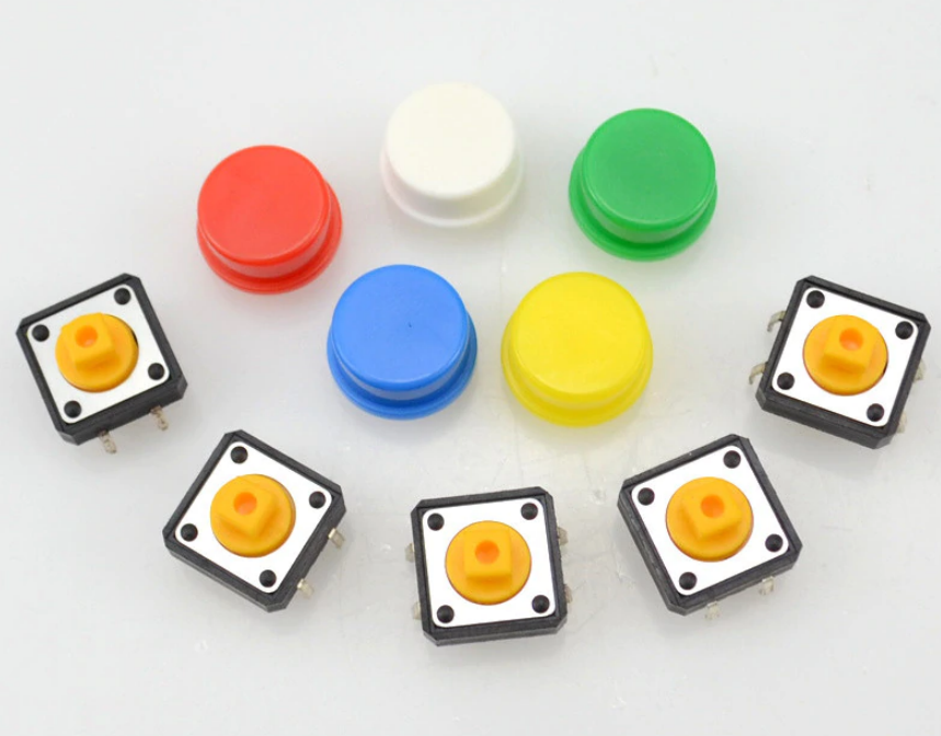
The button switch is an electronic switch. When we press the button, the switch function is turned on. When the pressure is removed, the switch is turned off. Its internal structure is realized by changing the force of the metal shrapnel.
In this project, we use a button switch and an LED to make a small desk lamp project. Press the button to turn on the LED, and press button to turn off the LED.
Working Principle
I believe that button switch is common and popular for people. It belongs to switch quantity( digital quantity)component. Composed of normally open contact and normally closed contact,its working principle is similar with ordinary switch.
When the normally open contact bears pressure, the circuit is on state ; however, when this pressure disappears, the normally open contact goes back to initial state, that is, off state. The pressure is the act we switch the button.
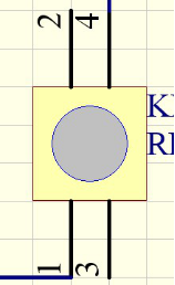
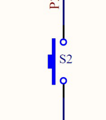
Schematic Diagrams:
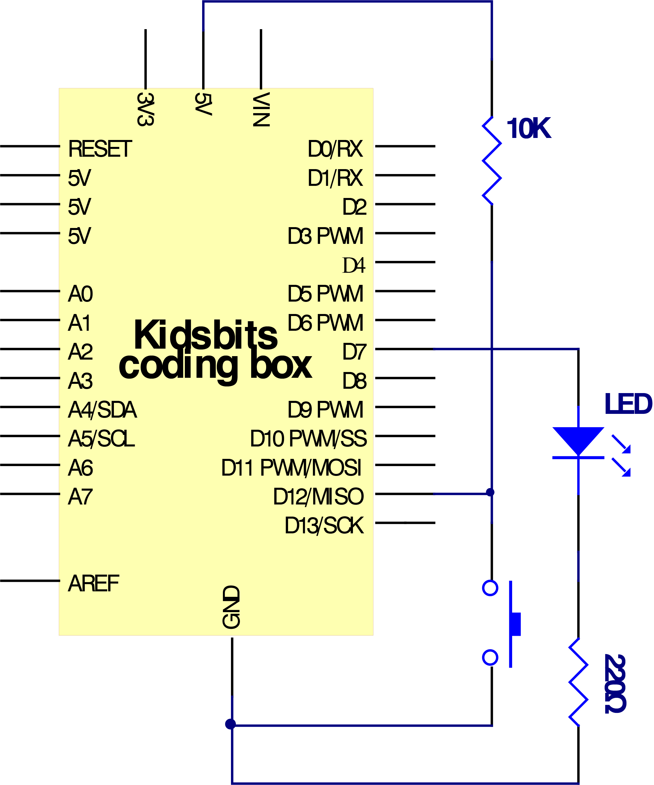
Circuit Connection
Project Code
  \*Kidsbits Coding Box

  Project 7

  Small desktop lamp

  http//www.kidsbits.cc

  */

  volatile int PushCounter;

  volatile int State;

  volatile int lastState;

  int ledpin=7;// initialize pin 7

  int inpin=12;// initialize pin 12

  void setup()

  {

  PushCounter = 0;

  State = 0;

  lastState = 0;

  pinMode(ledpin,OUTPUT);// set LED pin as “output”

  pinMode(inpin,INPUT);// set button pin as “input”

  }

  void loop()

  {

  State = digitalRead(inpin);

  if (State != lastState) {

  if (State == 1) {

  PushCounter = PushCounter + 1;

  }

  }

  delay(100);

  lastState = State;

  if(PushCounter%2==0)

  { digitalWrite(ledpin,HIGH);}

  else

  { digitalWrite(ledpin,LOW);}

  }

  //////////////////////////////////////////////////////////////////
Project Result
After uploading the code to the coding box, when the button at D12 is pressed once, the light at D7 is on;when the button is pressed again, the light at D7 goes out; the same working situation as the desk lamp.
next project***
Project 8: PIR Motion Alarm

Project Introduction
PIR motion sensor can detect infrared signals from a moving person or moving animal, and output switching signals. It can be applied to a variety of occasions to detect the movement of human body.
For example, in the corridor at night, the PIR motion sensor senses someone going upstairs, and the light turns on automatically, which is not only practical but also environmentally friendly.
PIR Motion Sensor Specification
Input Voltage 3.3 ~ 5V (6V Maximum)
Working Current 15uA
Working Temperature -20 ~ 85 ℃
Output Voltage High 3V, Low 0V
Output Delay Time (High Level) About 2.3 to 3 Seconds
Detection Angle 100 °
Detection Distance 7 meters
Output Indicator LED (When output HIGH, it will be ON)
Pin limit Current 100mA
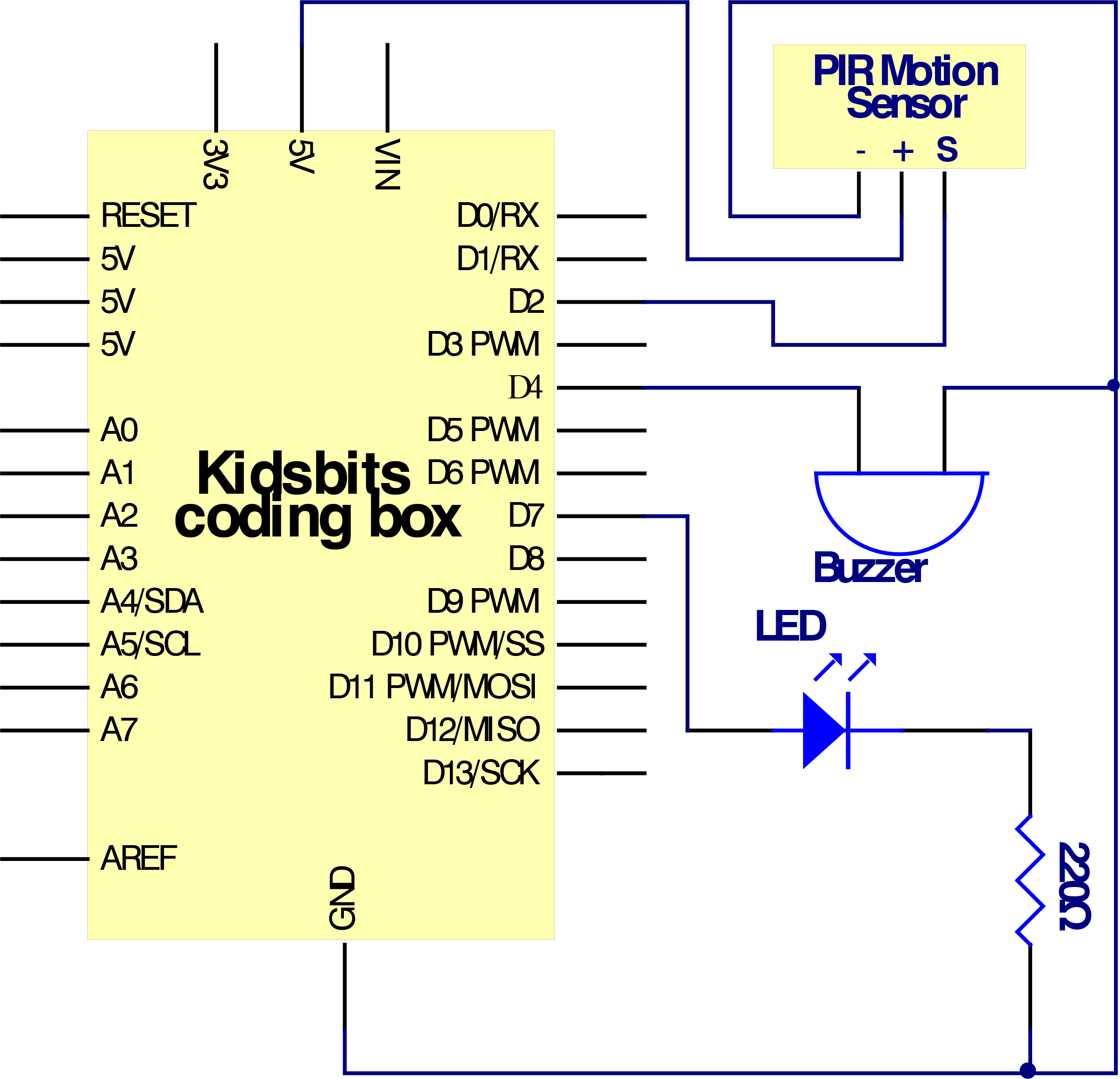
Circuit Connection
Project Code
  \*Kidsbits Coding Box

  Project 8

  PIR Motion Alarm

  http//www.kidsbits.cc

  */

  int Sensor_pin = 2; //define pin D2 of PIR sensor

  int Buzzerpin = 4; //Define the pin D4 of the buzzer

  int ledpin =7; //Define the pin D7 of the LED light

  void Alarm() //The buzzer sounds an alarm

  {

  for(int i=0;i\<100;i++)

  {

  digitalWrite(Buzzerpin,HIGH); //make a sound

  delay(2);

  digitalWrite(Buzzerpin,LOW); //No sound

  delay(2); //Modify the delay time, change the sound frequency

  }

  }

  void setup()

  {

  pinMode(Sensor_pin,INPUT); //Define PIR sensor interface as input

  pinMode(Buzzerpin,OUTPUT); //Define the buzzer interface as output

  pinMode(ledpin,OUTPUT); //Define the LED interface as output

  }

  void loop()

  {

  int val=digitalRead(Sensor_pin); //Define the parameter to store the state read
  by the PIR sensor

  if(val == 1) //If someone is detected (within the detection range)

  {

  Alarm();//The buzzer sounds an alarm

  digitalWrite(ledpin, HIGH); // LED flashes

  delay(10);

  digitalWrite(ledpin, LOW);

  delay(10);

  }

  else//If no person is detected

  {

  return;

  }

  delay(100); //delay 100 milliseconds

  }
//////////////////////////////////////////////////////////////////
Project Result
Uploading the code to the coding box, when the human infrared sensor detects people moving nearby,the LED starts flashing, the buzzer sounds. If no one is detected nearby, the LED is off and the buzzer does not sound.
next project***
Project 9: Reed switch
Project Introduction
Reed switch is basically an electrical switch which is operated when a magnetic field is brought near to it. It is made up of two small metal pieces kept inside a glass tube under vacuum. In a typical reed switch, two metal pieces will be made of a ferromagnetic material and covered with rhodium or ruthenium to give them long life. The switch will be activated when there is a presence of magnetic field around the switch.
Reed switch is used in many of the real-life applications such as magnetic door switch, laptops, smart phones etc.
Sensor Specification
There are two types of reed switch.
Normally open reed switch
Normally closed reed switch
In normally open reed switch, switch is open in the absence of magnetic field and it is closed in the presence of magnetic field. Under the presence of magnetic field, two metal contacts inside the glass tube attract each other to make contact.
In normally closed reed switch, switch is closed in the absence of magnetic field and it is open in the presence of magnetic field.
The glass enclosure of the two metal pieces protect them from dirt, dust and other particles. Reed switch can be operated in any environment such as environment where flammable gas is present or environment where corrosion would affect open switch contacts.
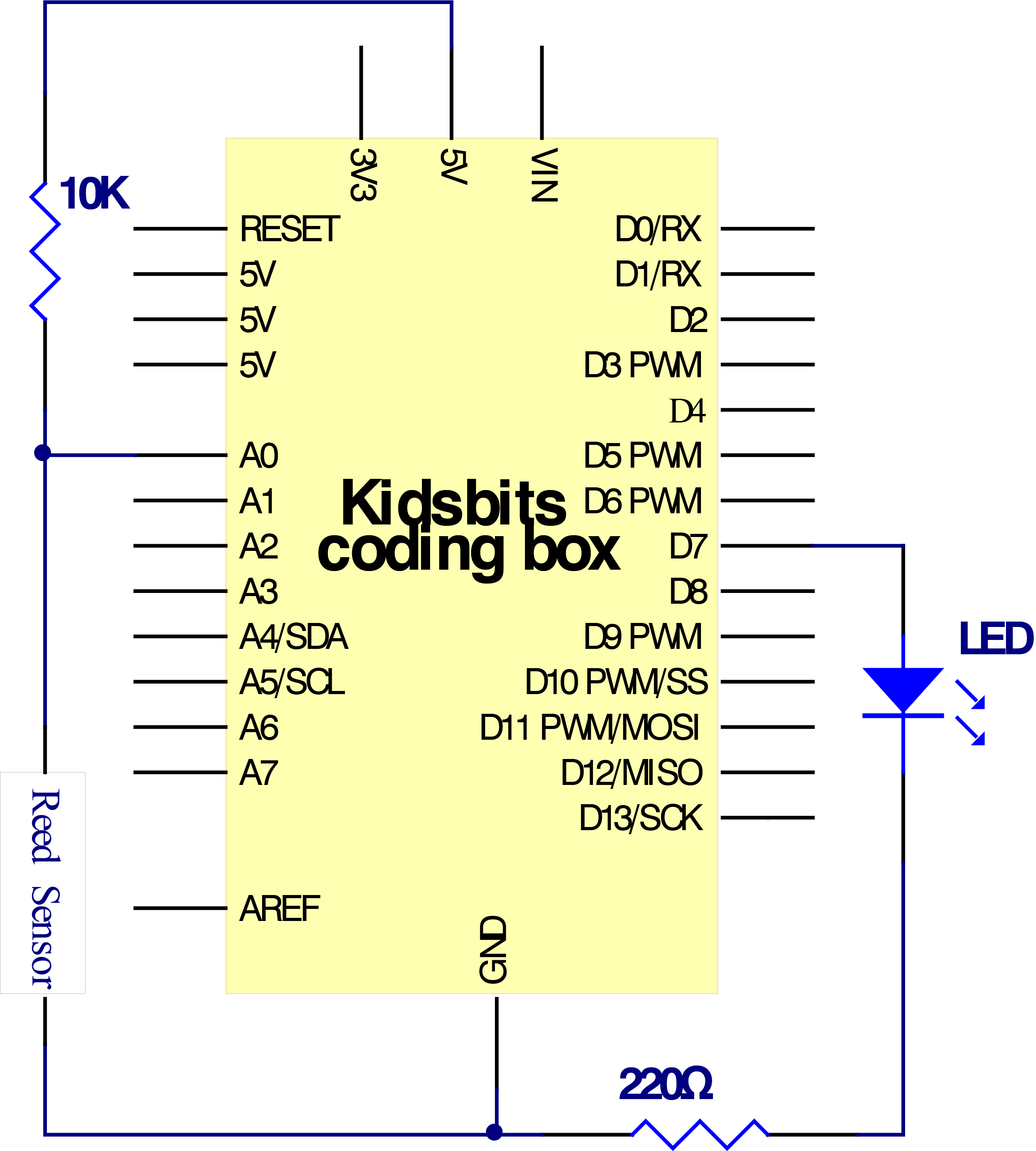
Circuit Connection
Project Code
  \*Kidsbits Coding Box

  Project 9

  Reed switch

  http//www.kidsbits.cc

  */

  int LED = 7;

  int reed_switch = A0;

  int reed_status;

  void setup()

  {

  pinMode(LED, OUTPUT);

  pinMode(reed_switch, INPUT);

  }

  void loop()

  {

  reed_status = digitalRead(reed_switch);

  if (reed_status == 1)

  digitalWrite(LED, LOW);

  else

  digitalWrite(LED, HIGH);

  }

  //////////////////////////////////////////////////////////
Project Result
After uploading the code to the coding box, when the magnetic reed detects nearby magnetic force, the LED lights up. If no magnetic force is detected, the LED is off.
next project***
Project 10: DC motor
Project Introduction
With this coding box, we can make our own adjustable fan.Usually a simple electric fan is made up of blade, motor and switch. You can see a motor fan module on the Kidsbits Coding Box. The motor is actually the electric motor. If there is electricity, the fan blade will rotate. The motor with the fan blade is also called a fan module. Inputting HIGH or LOW level to two pins of fan module, we can make fan rotate.
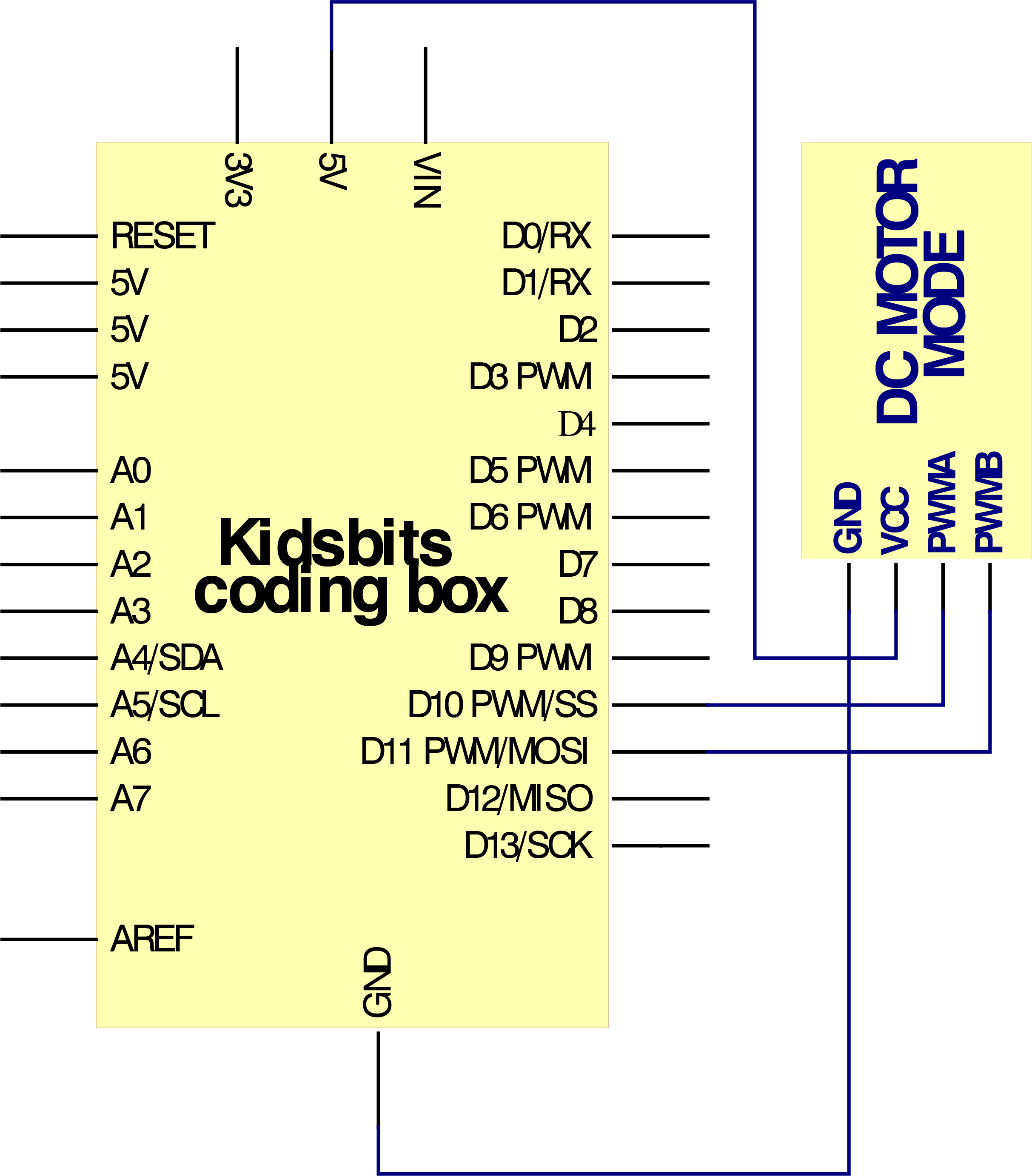
Connection Diagram
So set to D10, LOW; D11 to HIGH. Upload the code and motor fan will turn clockwise.
If we set the D10 to HIGH, D11 to LOW, the fan will turn anticlockwise.
If we set to D10 and D11 to LOW, the fan won’t turn.
Now, we’ve known how to control fan. But how about making fan rotate slowly? Here we can use PWM pins.
PWM pins can steadily output the HIGH and LOW level, and can continuously change HIGH or LOW in a regular time period. The D10 and 11 of motor fan are PWM pins. We can adjust the motor’s speed via PWM pins.
Project Code
  \*Kidsbits Coding Box

  Project 10

  small fan

  http//www.kidsbits.cc

  */

  // the setup function runs once when you press reset or power the board

  void setup() {

  // initialize digital pin 10 11 as output.

  pinMode(10, OUTPUT);

  pinMode(11, OUTPUT);

  digitalWrite(10, LOW);

  digitalWrite(11, LOW);

  }

  // the loop function runs over and over again forever

  void loop() {

  analogWrite(10, 150);

  digitalWrite(11, LOW);

  delay(1000);

  digitalWrite(10, LOW);

  digitalWrite(11, LOW);

  delay(3000);

  digitalWrite(10, LOW);

  analogWrite(11, 150);

  delay(1000);

  digitalWrite(10, LOW);

  digitalWrite(11, LOW);

  delay(3000);

  }

  //////////////////////////////////////////////////////////
Project Result
After uploading the code to the coding box, the motor on the coding box rotates clockwise for 1 second, with a delay of 3 seconds.Then turn counterclockwise for 1 second, delay 3 seconds, and loop.
next project***
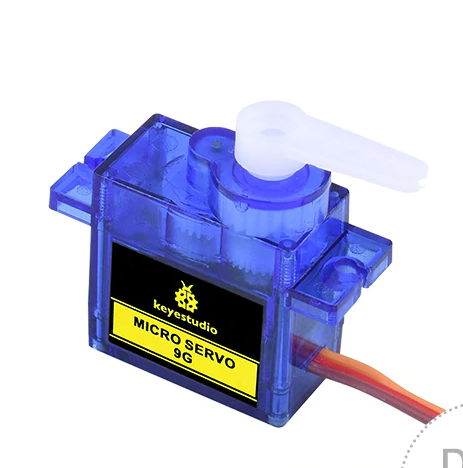
Project 11: Servo
Project Introduction
Servo is a position (angle) servo drive, which is suitable for those control systems that require constant angle changes and can be maintained. It has been widely used in remote control toys, airplane models, submarine models, and remote control robots.
In this project, we use the servo rotation angle change to DIY a car speed dial. You can intuitively understand the servo’s movement trajectory.
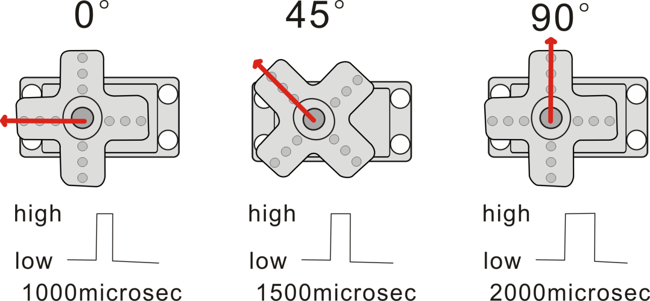
Working Principle
Servo is composed of rudder disc, position feedback potentiometer, reduction gear set, DC motor and control circuit. The reduction gear set is driven by a DC motor, and its output shaft drives a position feedback potentiometer with linear proportional characteristics as position detection. According to the feedback voltage of the potentiometer, the control circuit compares with the external input control pulse, generates a correction pulse, controls and drives the DC motor to rotate forward or reverse, so that the output position of the reduction gear is combined with the desired value. So as to achieve the purpose of accurately controlling the steering angle.
Servo’s control pulse cycle is 20ms, and the pulse width ranges from 0.5ms to 2.5ms, corresponding to positions from -90 degrees to +90 degrees, taking a 180 degree angle servo as an example
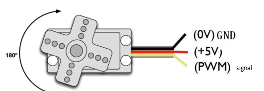
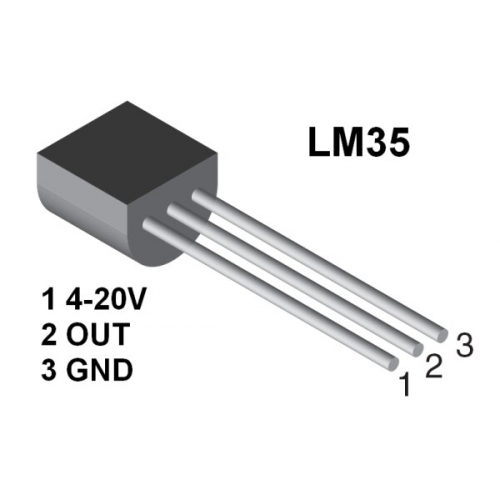
Servo motor comes with many specifications. But all of them have three connection wires, distinguished by brown, red, orange (different brand may have different color).
Brown one is for GND, red one for power positive, orange one for signal line.
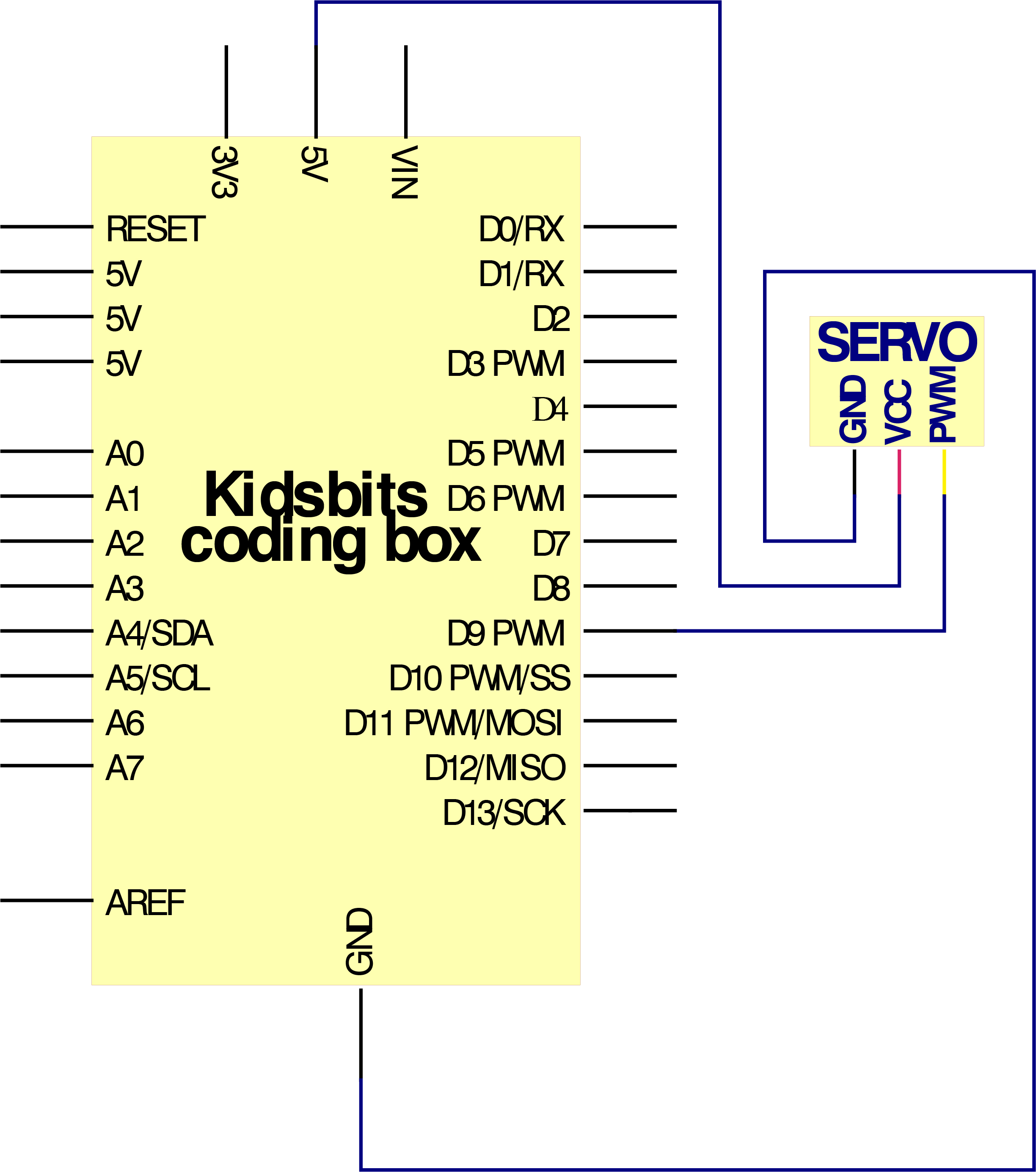
Connection Diagram
Project Code
  \*Kidsbits Coding Box

  Project 11

  Servo

  http//www.kidsbits.cc

  */

  \#include \<Servo.h\>

  Servo myservo;// define servo variable name

  void setup()

  {

  myservo.attach(9);// select servo pin(9 or 10)

  }

  void loop()

  {

  myservo.write(0);// set rotate angle of the motor

  delay(500);

  myservo.write(45);// set rotate angle of the motor

  delay(500);

  myservo.write(90);// set rotate angle of the motor

  delay(500);

  myservo.write(135);// set rotate angle of the motor

  delay(500);

  myservo.write(180);// set rotate angle of the motor

  delay(500);

  }//////////////////////////////////////////////////////////
Above are the two methods to control the servo. You can choose either one according to your liking or actual need.
Project Result
After uploading the code to the coding box, the servo rotates, the angle starts from 0°, increases by 45° every 0.5 seconds, and when it reaches 180°, it turns to the 0° position.
next project***
Project 12: Potentiometer
Project Introduction
The potentiometer is an electronic component that we are very familiar with. It is an analog component. The switch for adjusting the volume on the electrical appliance and the button for adjusting the wind on the fan are all applications of the potentiometer.
In this project, we are going to learn how to use Arduino to read the value of the potentiometer, and then cooperate with the LED light to make a Dimming table lamp.
Features
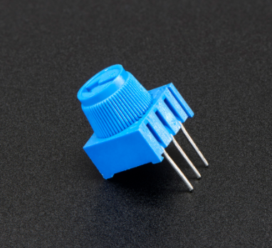
Adjustable potentiometer is just a kind of resistor. The resistance is changed by rotating the potentiometer, so is the voltage, speed, brightness and temperature. It is an analog electronic component, which has two states of 0 and 1(high level and low level). The analog quantity is different. Its data state presents a linear state such as 1 to 1000.
Read Values
We connect the adjustable potentiometer to the analog pin of Arduino to read its value. Please refer to the following wiring diagram for wiring.
\*Kidsbits Coding Box
Project 12.1
Read Potentiometer value
http//www.kidsbits.cc
*/
int potpin=A7;// initialize analog pin A7
int val=0;// define val, assign initial value 0
void setup()
{
Serial.begin(9600);// set baud rate at 9600
}
void loop()
{
val=analogRead(potpin);// read the analog value of analog pin 0, and assign it
to val
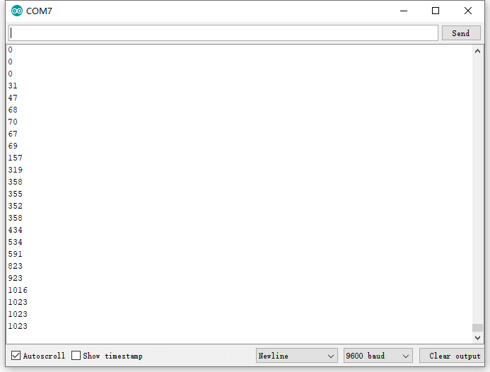
Serial.println(val);// display val’s value
}
//////////////////////////////////////////////////////////////////
When you rotate the potentiometer knob, you can see the displayed value change. The reading of analog value is a very common function since most sensors output analog value. After calculation, you can get the corresponding value you need.
Below figure shows the analog value it reads.
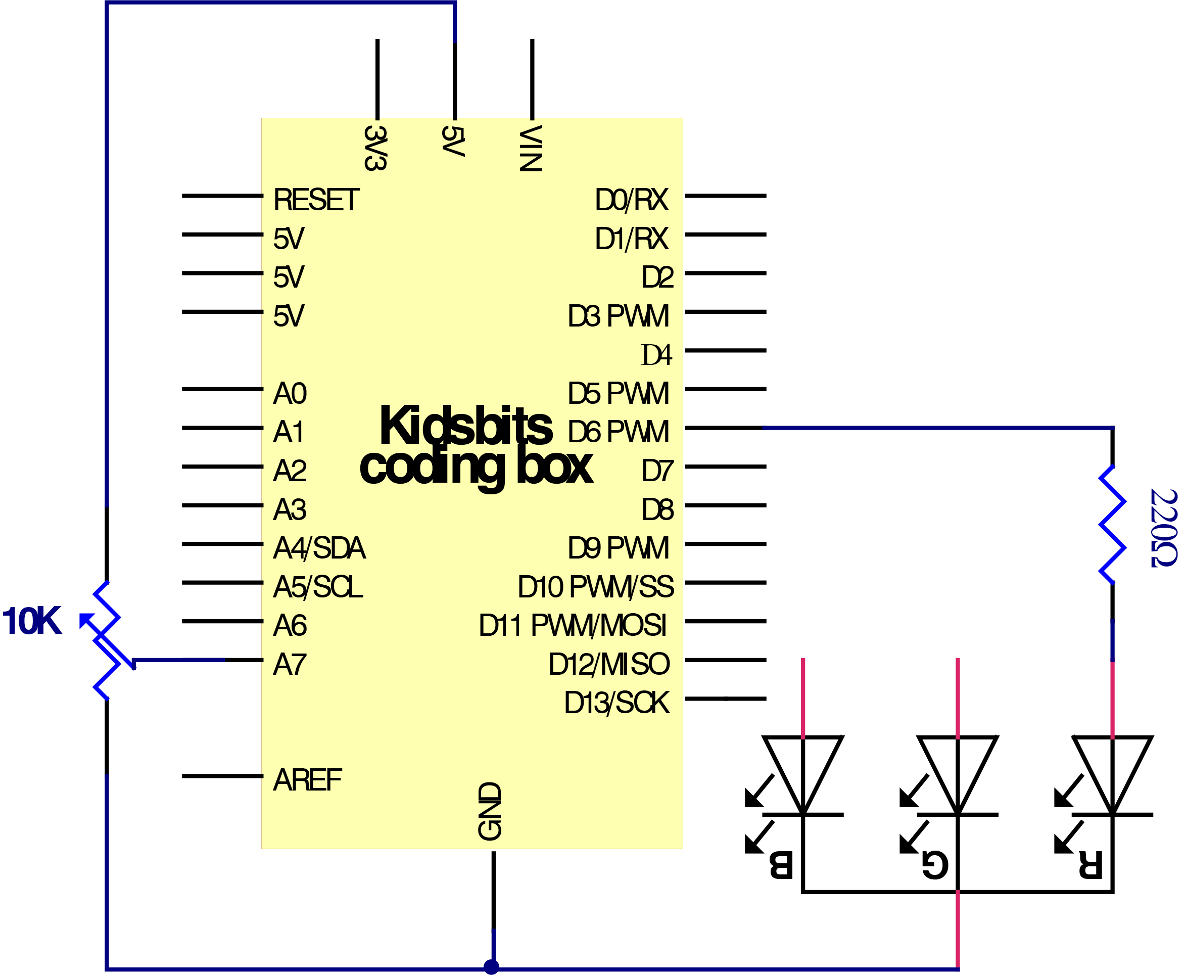
Circuit Connection
In the last step, we read the value of the potentiometer, and now we need to convert the value of the potentiometer into the brightness of the LED to make a small desk lamp with adjustable brightness. See the wiring diagram.
Project Code
  \*Kidsbits Coding Box

  Project 12.2

  Dimming table lamp

  http//www.kidsbits.cc

  */

  int potpin=A7;// initialize analog pin 7

  int ledpin=6;//initialize digital pin 6(PWM output)

  int val=0;// Temporarily store variables' value from the sensor

  void setup()

  {

  pinMode(ledpin,OUTPUT);// define digital pin 6 as “output”

  Serial.begin(9600);// set baud rate at 9600

  // attention: for analog ports, they are automatically set up as “input”

  }

  void loop()

  {

  val=analogRead(potpin);// read the analog value from the sensor and assign it to
  val

  Serial.println(val);// display value of val

  analogWrite(ledpin,val/4);// turn on LED and set up brightness(maximum output
  of PWM is 255)

  delay(10);// wait for 0.01 second

  }

  //////////////////////////////////////////////////////////
Project Result
After uploading the code to the coding box, you can control the brightness of the red LED in the RGB through the potentiometer.
next project***
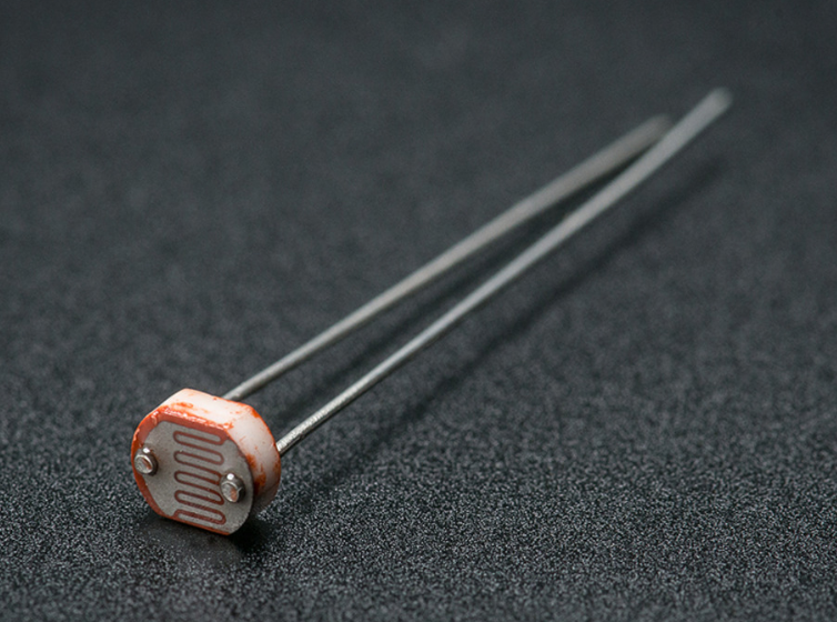
Project 13: Light
Project Introduction
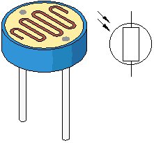
Photocell is a resistor whose resistance varies from different incident light strength. It’s based on the photoelectric effect of semiconductor. If the incident light is intense, its resistance reduces; if the incident light is weak, the resistance increases.
We use the characteristics of Photocell to make a light-controlled table lamp. When the light is dimmed, the light turns on.
Photocell Little Knowledge
Photocell is commonly applied in the measurement of light, light control and photovoltaic conversion (convert the change of light into the change of electricity).
Photocell is also being widely applied to various light control circuits, such as light control and adjustment, optical switches, etc.
We will start with a relatively simple experiment regarding to photovaristor application.
Photocell is an element that can change its resistance as light strength changes. So need to read the analog value. You can refer to the PWM experiment, replacing the potentiometer with photocell`. When there is change in light strength, it will make corresponding change on the LED.
Read Photocell value
We first use a simple code to read the value of the photocell, print it in the serial monitor, and wire it as shown below.
  \*Kidsbits Coding Box

  Project 13.1

  Read Photocell value

  http//www.kidsbits.cc

  */

  int photocellpin=A6;// initialize analog pin 6, connected with photocell

  int val=0;// initialize variable va

  void setup()

  {

  Serial.begin(9600);// set baud rate at “9600”

  }

  void loop()

  {

  val=analogRead(photocellpin);// read the value of the sensor and assign it to
  val

  Serial.println(val);// display the value of val

  delay(1000);// wait for 1 s

  }

  //////////////////////////////////////////////////////////////////
Upload the code to the PLUS development board, open the serial monitor, and then you can read the current photocell value.We put our hands on the photocell, and the value became larger.
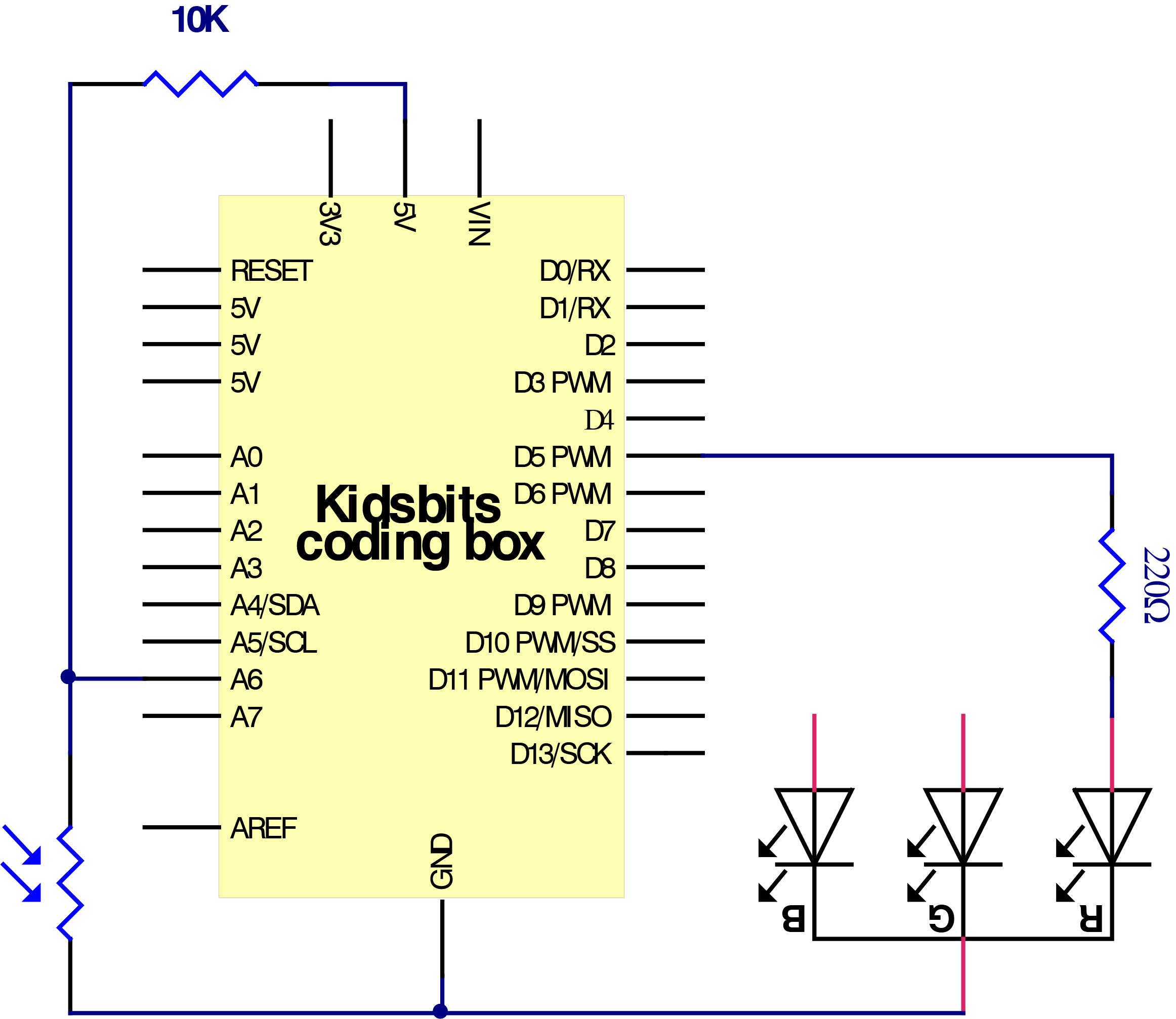
Circuit Connection
We made a small dimming table lamp before, and now we want to make a light-controlled small table lamp. The basic principles of the two are the same. Both are obtained by obtaining the analog value of the sensor and then adjusting the brightness of the LED.
Project Code
  \*Kidsbits Coding Box

  Project 13.2

  Light control LED

  http//www.kidsbits.cc

  */

  int potpin=6;// initialize analog pin 6, connected with photocell

  int ledpin=5;// initialize digital pin 5,

  int val=0;// initialize variable va

  void setup()

  {

  pinMode(ledpin,OUTPUT);// set digital pin 11 as “output”

  Serial.begin(9600);// set baud rate at “9600”

  }

  void loop()

  {

  val=analogRead(potpin);// read the value of the sensor and assign it to val

  Serial.println(val);// display the value of val

  analogWrite(ledpin,val/4);// set up brightness(maximum value 255)

  delay(10);// wait for 0.01s

  }

  //////////////////////////////////////////////////////////////////
Project Result
After uploading the code to the coding box, the photoresistor can detect the intensity of the light. The brighter the light, the brighter the red LED in RGB.
next project***
Project 14: Sound

Project Introduction
The sound sensor is a common sensor. It has a built-in capacitive electret microphone and power amplifier. It can be used to detect the sound intensity of the environment.
In this project, we use a sound sensor and a DC motor to make a voice-activated smart fan. When we make a sound, the fan starts.
Sound Sensor
Sound sensor is typically used in detecting the loudness in ambient environment. The Arduino can collect its output signal by analog input interface.
The S pin is analog output, that is voltage signal real-time output of microphone. The sensor comes with a potentiometer, so that you can turn it to adjust the signal gain.
It also has a fixed hole so that you can mount the sensor on any other devices. You can use it to make some interactive work, such as a voice operated switch.
Read Sound Sensor Value
We first use a simple code to read the value of the sound sensor, print it in the serial monitor, and wire it as shown below.
  \*Kidsbits Coding Box

  Project 14.1

  Read Sound Sensor value

  http//www.kidsbits.cc

  */

  int soundpin=A2;// initialize analog pin 2, connected with sound sensor

  int val=0;// initialize variable va

  void setup()

  {

  Serial.begin(9600);// set baud rate at “9600”

  }

  void loop()

  {

  val=analogRead(soundpin);// read the value of the sensor and assign it to val

  Serial.println(val);// display the value of val

  delay(1000);// wait for 1 s

  }

  //////////////////////////////////////////////////////////////////
Upload the code to the PLUS development board, open the serial monitor, blow or clap your hands at the sensor, you can see the sensor’s value changes significantly.
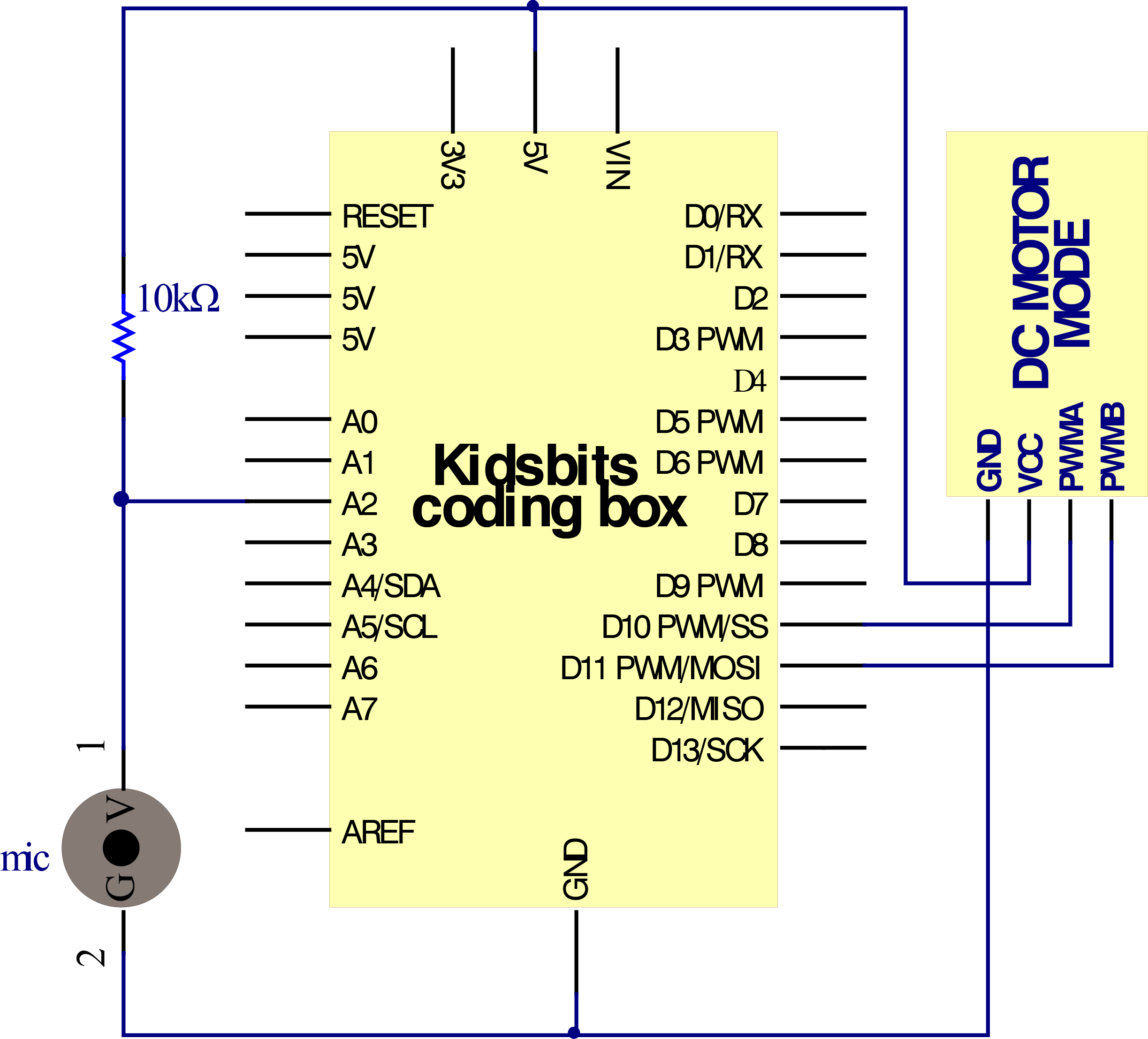
Connection Diagram
Next, we formally enter this project. We use a sound sensor and a small motor to make a sound-activated fan. Connect to the circuit diagram below.
Project Code
  \*Kidsbits Coding Box

  Project 14.2

  Voice-activated smart fan

  http//www.kidsbits.cc

  */

  void setup() {

  Serial.begin(9600);

  // initialize digital pin 10 11 as output.

  pinMode(10, OUTPUT);

  pinMode(11, OUTPUT);

  digitalWrite(10, LOW);

  digitalWrite(11, LOW);

  }

  void loop() {

  int Soundvalue = analogRead(A2); // read the input analog value

  Serial.println(Soundvalue);

  if(Soundvalue\>650)

  {

  analogWrite(10, 150);

  digitalWrite(11, LOW);

  delay(1000);

  }

  else{

  digitalWrite(10, LOW);

  digitalWrite(11, LOW);

  }

  }

  //////////////////////////////////////////////////////////
Project Result
After uploading the code to the coding box. success, the microphone sensor can detect the sound. When the value of the sound is greater than 650, the motor fan starts to rotate. If it does not reach 650, the motor fan does not rotate.
next project***
Project 15: Gas Sensor

Project Introduction
MQ-2 Gas Sensor module is useful for gas leakage detecting in homes and industries. It can detect LPG, i-butane, propane, methane, alcohol, hydrogen and smoke.
Sensor Specification
Whenever the concentration of gas increases the resistance will decrease (but the current flow will get increased). It leads to change in voltage and it is read at Analog out pin which tells how much gas is concentrated in normal Air. This varied analog voltage is used to calculate the PPM of Gas.
Similarly, the Module has a Digital output (connected with an Op-Amp) along with a Potentiometer. The Threshold/Sensitivity can be adjusted using the Potentiometer. Because to calibrate the sensor to an Idle condition. Once it reaches the threshold, it will produce the output signal at D0 Pin.
Note: All MQ Sensor takes some time to work properly because of the Heater needs to be heated for a while.
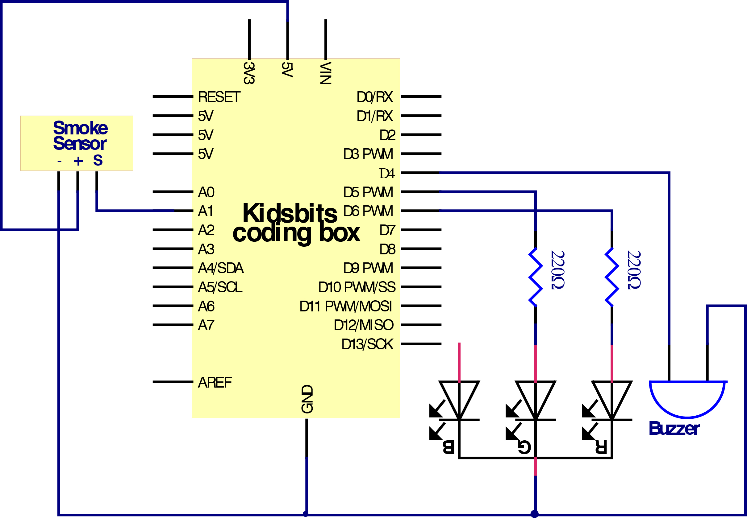
Circuit Connection
Project Code
  \*Kidsbits Coding Box

  Project 15

  Gas Sensor

  http//www.kidsbits.cc

  */

  int redLed = 6;

  int greenLed = 5;

  int buzzer = 4;

  int smokeA0 = A1;

  // Enter Your threshold value

  int sensorThres = 400;

  void setup() {

  pinMode(redLed, OUTPUT);

  pinMode(greenLed, OUTPUT);

  pinMode(buzzer, OUTPUT);

  pinMode(smokeA0, INPUT);

  Serial.begin(9600);

  }

  void loop() {

  int analogSensor = analogRead(smokeA0);

  Serial.print("Sensor Value from A0: ");

  Serial.println(analogSensor);

  // Checks if it has reached the threshold value

  if (analogSensor \> sensorThres)

  {

  digitalWrite(redLed, HIGH);

  digitalWrite(greenLed, LOW);

  tone(buzzer, 1000, 200);

  }

  else

  {

  digitalWrite(redLed, LOW);

  digitalWrite(greenLed, HIGH);

  noTone(buzzer);

  }

  delay(100);

  }
Project Result
After uploading the code to the coding box, the gas sensor can detect combustible gas. After detecting combustible gas, the buzzer will issue an alarm and the light on RGB will be red. If no combustible gas is detected, the buzzer will not make a sound, and the light on it lights up green.
next project***
Project 16: Temperature Tester
Project Introduction
LM35 is a common and easy-to-use temperature sensor. It does not require other hardware. You just need an analog port to make it work. The difficulty lies in compiling the code to convert the analog value it reads into Celsius temperature.
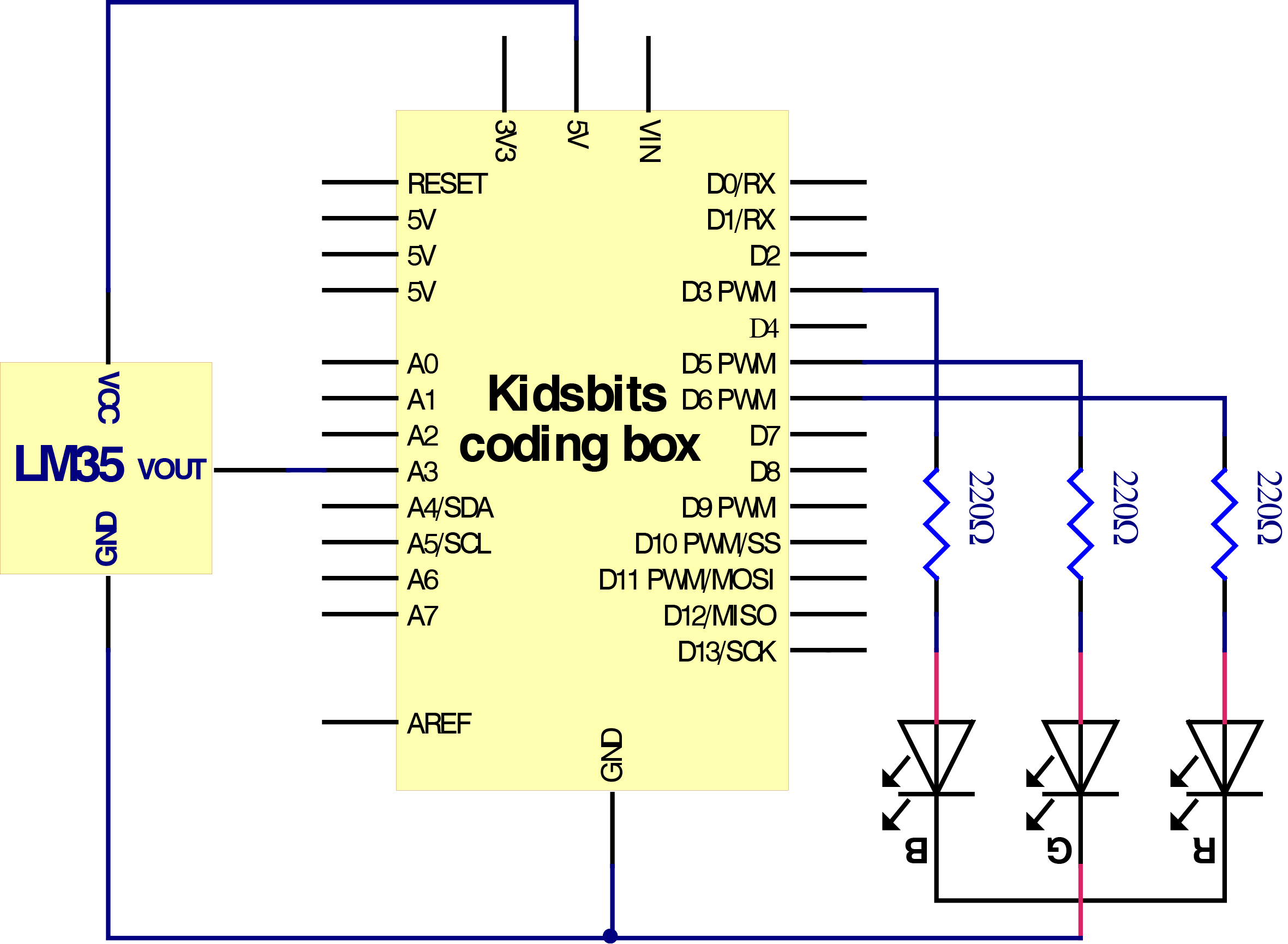
In this project, we use a temperature sensor and 3 LED lights to DIY a temperature tester. When the temperature sensor touches different temperature objects, the LED lights will show different colors.
Working Principle
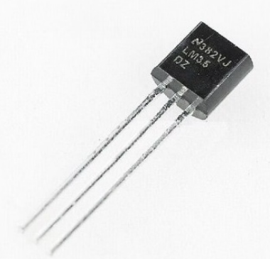
LM35 is a widely used temperature sensor with many different package types. At room temperature, it can achieve the accuracy of ±1/4°C without additional calibration processing.
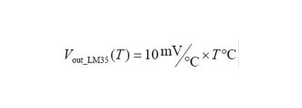
LM35 temperature sensor can produce different voltage by different temperature
When temperature is 0 ℃, it outputs 0V; if increasing 1 ℃, the output voltage will increase 10 mv.
The output temperature is 0℃~100℃, the conversion formula is as follows:
Read temperature value
We first use a simple code to read the value of the temperature sensor, print it in the serial monitor, and wire it as shown below.
Here, LM35 output is given to analog pin A0 of Plus board. This analog voltage is converted to its digital form and processed to get the temperature reading.
\*Kidsbits Coding Box
Project 16.1
Read temperature value
http//www.kidsbits.cc
*/
void setup()
{
Serial.begin(9600);//Set Baud Rate to 9600 bps
}
void loop()
{ unsigned int val;
unsigned int dat;
val=analogRead(3);//Connect LM35 on Analog 3
dat=(500 val) /1024;
Serial.print("Temp:"); //Display the temperature on Serial monitor
Serial.print(dat);
Serial.println("C");
delay(500);
}
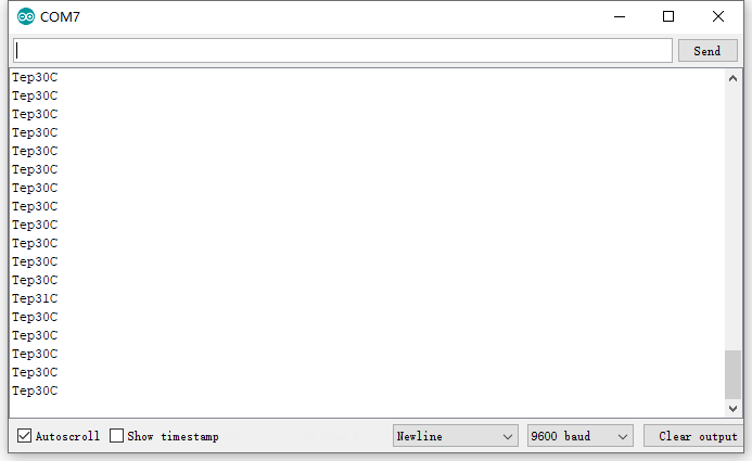
//////////////////////////////////////////////////////////////////
Upload the code to the PLUS development board, open the serial monitor, and then you can read the current temperature value.
Circuit Connection
Now use the LM35 temperature sensor and 3 LEDs to do a temperature tester. When the temperature tester senses different temperatures, different LEDs will light up. Follow the diagram below for wiring.
Project Code
  \*Kidsbits Coding Box

  Project 16.2

  Temperature tester

  http//www.kidsbits.cc

  */

  int redpin = 6; //select the pin for the red LED

  int greenpin =5;// select the pin for the green LED

  int bluepin =3; // select the pin for the blue LED

  void setup()

  {

  pinMode(redpin, OUTPUT);

  pinMode(bluepin, OUTPUT);

  pinMode(greenpin, OUTPUT);

  Serial.begin(9600);//Set Baud Rate to 9600 bps

  }

  void loop()

  { unsigned int val;

  unsigned int dat;

  val=analogRead(3);//Connect LM35 on Analog 3

  dat=(500 val) /1024;

  Serial.print("Temp:"); //Display the temperature on Serial monitor

  Serial.print(dat);

  Serial.println("C");

  if (dat \>= 50) {

  digitalWrite(greenpin, LOW);

  digitalWrite(bluepin, LOW);

  digitalWrite(redpin, HIGH);

  }

  else if (dat \>= 30 && dat \< 50) {

  digitalWrite(greenpin, LOW);

  digitalWrite(bluepin, HIGH);

  digitalWrite(redpin, LOW);

  }

  else {

  digitalWrite(greenpin, HIGH);

  digitalWrite(bluepin, LOW);

  digitalWrite(redpin, LOW);

  }

  delay(200);

  }

  //////////////////////////////////////////////////////////////////
Project Result
After uploading the code to the coding box, the temperature sensor can detect the outside temperature.
When the temperature is greater than or equal to 50°C, the RGB LED lights up red;
When the temperature is greater than or equal to 30°C and less than 50°C, the RGB LED lights up green;
When the temperature is less than 30°C, the RGB LED lights up blue,
You can use this item to make a temperature reminder water cup.
next project***
Project 17 Turns An LED On
Project Introduction
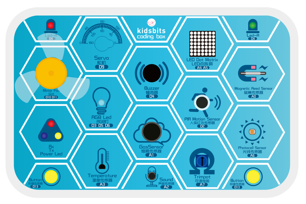
Dot matrices seem to be very unfamiliar, but in fact it is everywhere in our lives. It is widely used in some outdoor billboards, game consoles, and supermarkets.
And a LED dot matrix has many advantages, such as power saving, long service life, low cost, high brightness, wide viewing angle, long visual range, waterproof and so on. It can meet different needs, so it has great prospects.
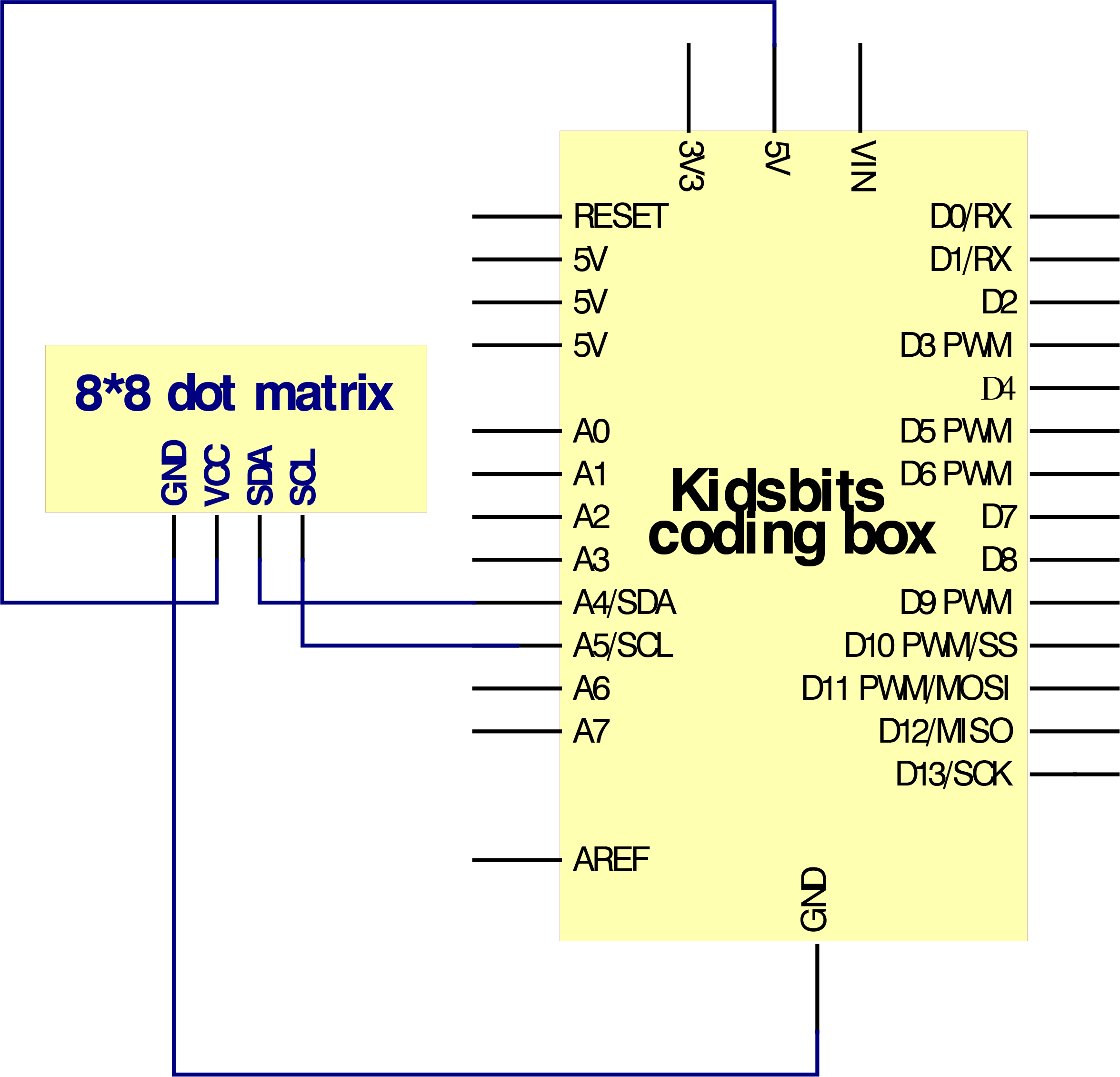
The 88 dot matrix integrated on the coding box uses I2C communication. It can control up to 64 LEDs and display interesting patterns, including numbers, characters, and graphics with only two signal pins.
What’s more, the 88 dot matrix is equipped with a HT16K33 driver chip .Through a simple I2C interface, we can control the chip to work and drive the 88 dot matrix screen.
Now we are about to start many 88 dot matrix projects. Firstly, let’s turn on a led on the dot matrix.
Project Circuit:
Project Principle:
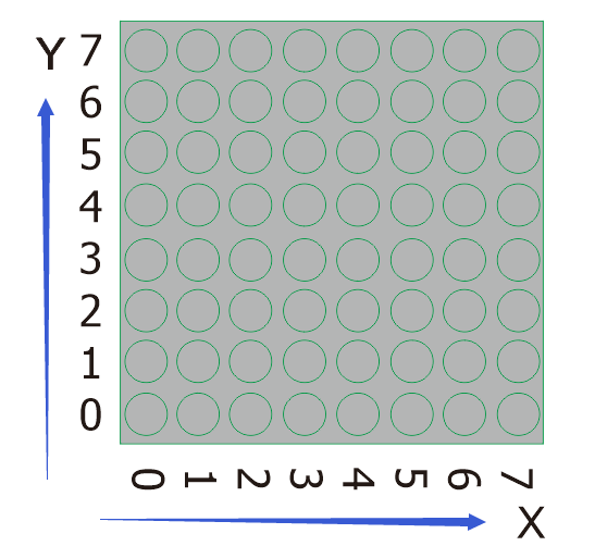
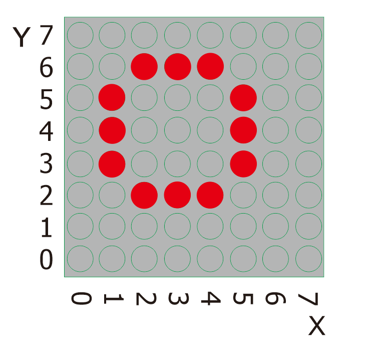
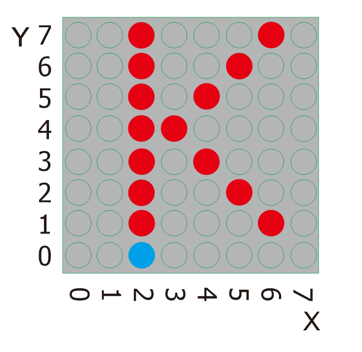
The theory behind the 88 dot matrix is quite simple. It is driven by the chip HT16K33 of the micro-controller. It has 64 LEDs, sitting in 8 rows and 8 columns. In order to locate these LEDs quickly, as the figure shown below, we can regarded this matrix as a coordinate system and create two aces by marking those in rows from 0 to 7 from bottom to top, and the ones in columns from 0 to 7 from the left to the right.
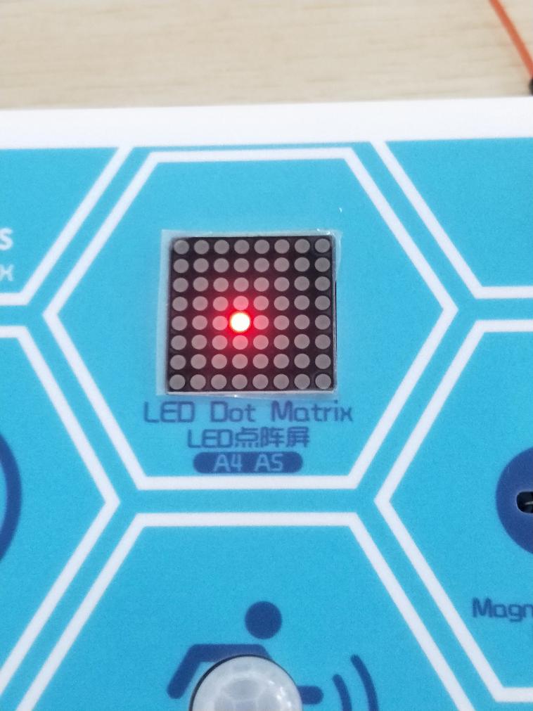
Then,what we should do to light a LED ?
Please have a look at the following picture.
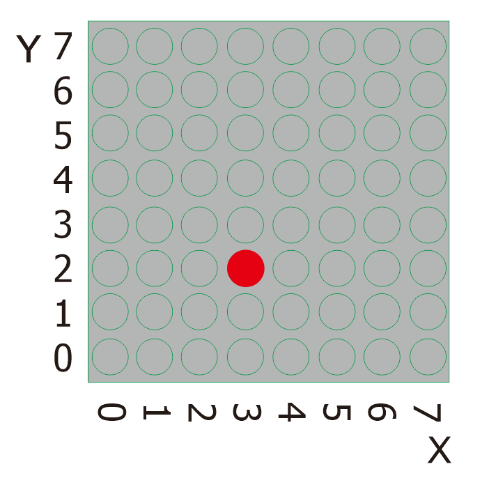
According to coordinate system created, the red spot in the above picture can be recorded as (3,2). Then we integrate its position into the code to write the following code.
Project Code:
  \*Kidsbits Coding Box

  Project 17

  88 dot matrix-turn on a LED

  http//www.kidsbits.cc

  */

  \#include <ks_Matrix.h\>

  Matrix myMatrix(A4,A5);

  void setup() {

  myMatrix.begin(112);

  myMatrix.clear();

  }

  void loop() {

  myMatrix.drawPixel(3,2,HIGH);

  myMatrix.writeDisplay();

  }
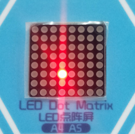
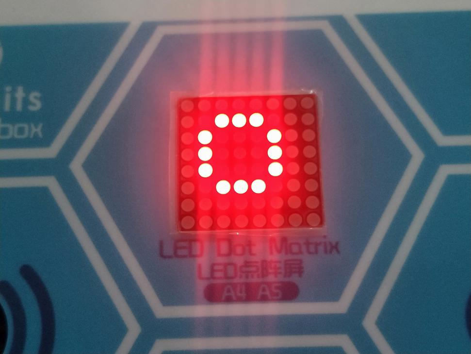
Project Result:
Upload the code to the coding box successfully, the LED dot matrix will display the required LED as shown in the figure below.
next project***
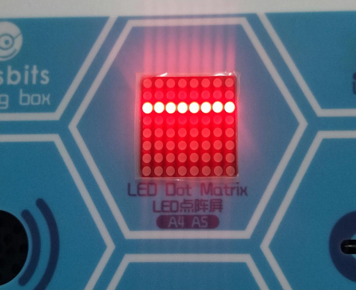
Project 18 Turn On A Line
Project Introduction
In the previous project, we have turned on one LED while in this lesson we will light a row of LEDs, that’s 8 LEDs.
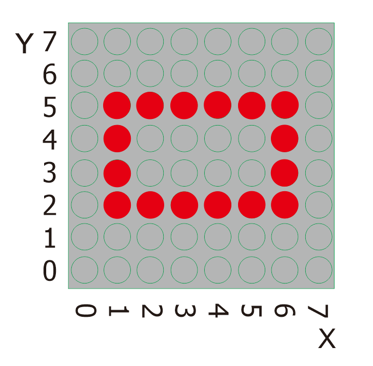
Project Principle:
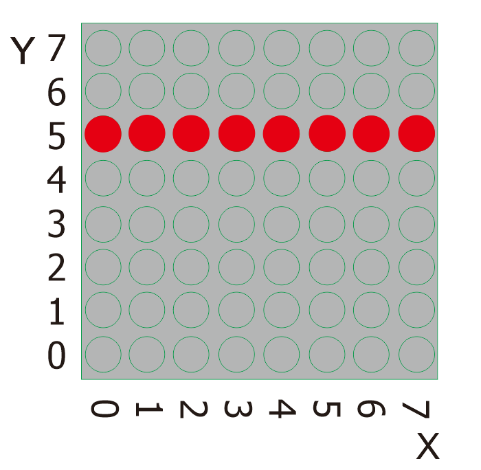
Please look at the above picture. What we can do to light this whole line of red spots? The solution we resort to is a function, matrix.drawLine. We just need to input the position of the starting and ending points of this a row of LEDs.
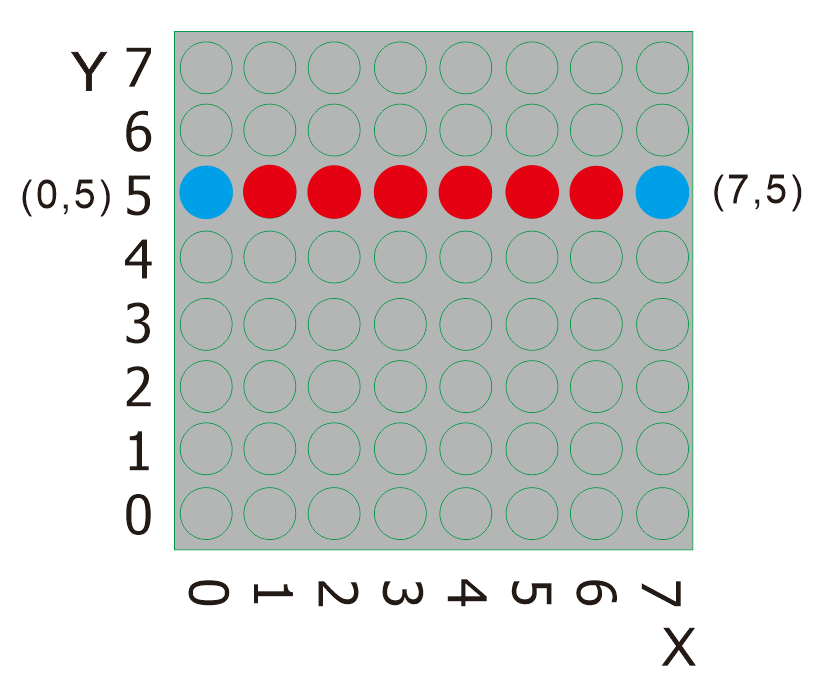
From the figure above, it is clear that the starting point of this line is (0,5) and the ending point is (7,5). Then we log them and place them into the code.
Project Code:
  \*Kidsbits Coding Box

  Project 18

  88 dot matrix-turn on a line

  http//www.kidsbits.cc

  */

  \#include <ks_Matrix.h\>

  Matrix myMatrix(A4,A5);

  void setup()

  {

  myMatrix.begin(112);

  myMatrix.clear();

  }

  void loop()

  {

  myMatrix.drawLine(0, 5, 7, 5, HIGH);

  myMatrix.writeDisplay();

  }
Project Result:
Upload the code to the coding box successfully, the LED dot matrix will display as shown in the figure below.
next project***
Project 19 Display A Rectangle
Project Introduction
Are you getting more excited about our next project?
This time, we intend to make it more challenging and let the matrix display a rectangle.
Project Principle:
Likewise, please eye the picture above.
What we should do to light all these red spots shaped in a rectangle? Our solution is another function, matrix.fillRect. With the help of this function, to showcase a rectangle or a square with these LEDs, we just need to determine the position of a starting point.
Let’s find the position of the blue spot,the starting point, in the picture below.
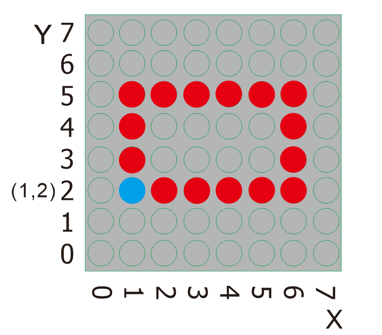
It is explicit that the position of the blue spot is (1,2). To light this rectangle, what required to do is adding the dimension of the rectangle behind the position value of this point. Therefore, for this rectangle, it is (1,2,6,4). Likewise, if we use this blue sport as a starting point to achieve a square with the dimension of 44, it is (1,2,4,4).
Project Code:
  \*Kidsbits Coding Box

  Project 19

  88 dot matrix-turn on a rectangle

  http//www.kidsbits.cc

  */

  \#include <ks_Matrix.h\>

  Matrix myMatrix(A4,A5);

  void setup() {

  myMatrix.begin(112);

  myMatrix.clear();

  }

  void loop() {

  myMatrix.drawRect(1, 2, 6, 4, HIGH);

  myMatrix.writeDisplay();

  }
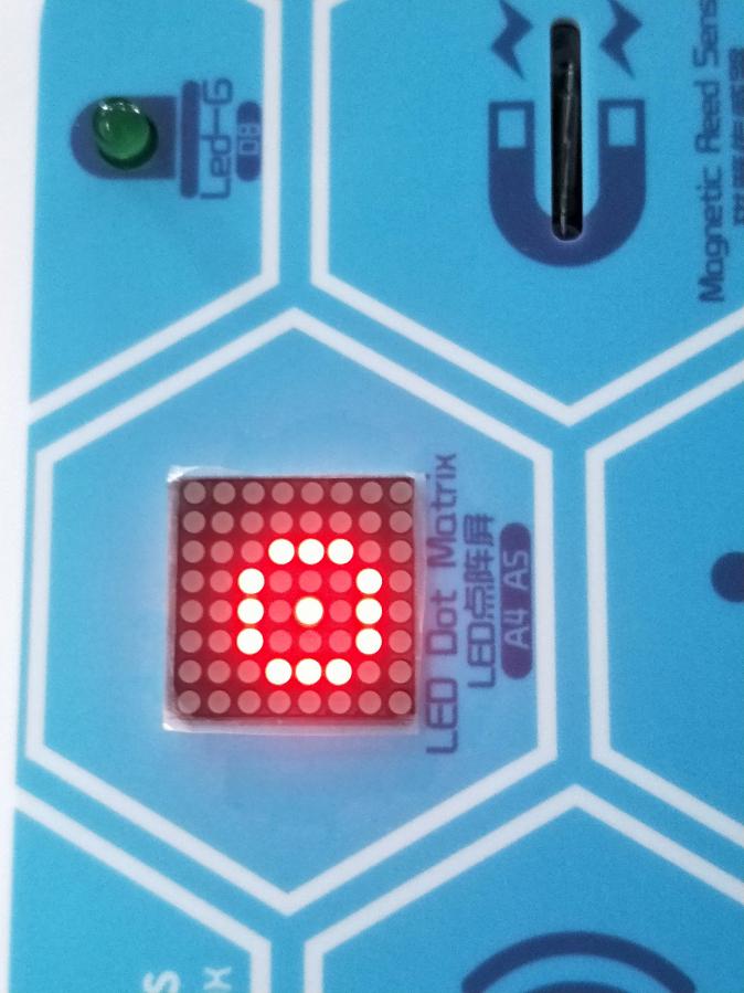
Project Result:
Upload the code to the coding box successfully, the LED dot matrix will display the pattern as shown in the figure below.
next project***
Project 20 Display A Circle
Project Introduction
In the previous project, the matrix has shown a rectangle with its LEDs. In this one, we will help it exhibit a circle. Working Principle
As the picture shown below, the circle we plan to create is 2 units in radius.
However, to achieve this goal by applying the knowledge learned before, we can only light them one by one, which is very time-consuming. We have a better and simpler way. That’s come to another function, matrix.drawCircle for help.
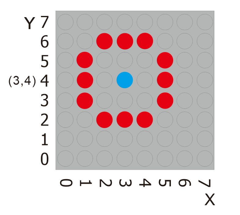
What we should do is to find the central point of a circle and mark its position as well as record the radius of the circle. In this case, the central point is (3,4) and the radius is 2 units. We combine these data together to obtain value (3,4,2) and add it to the code.
Therefore, if we want to draw a circle 3 units in radius with the same point, just alter the value to(3,4,3).
The following is the code.
Project Code
  \*Kidsbits Coding Box

  Project 20

  88 dot matrix-turn on a LED

  http//www.kidsbits.cc

  */

  \#include <ks_Matrix.h\>

  Matrix myMatrix(A4,A5);

  void setup() {

  myMatrix.begin(112);

  myMatrix.clear();

  }

  void loop() {

  myMatrix.drawCircle(3, 4, 2, HIGH);

  myMatrix.writeDisplay();

  }
Project Result:
Upload the code to the coding box successfully, the LED dot matrix will display as shown in the figure below.
next project***
Project 21 Display Text and Numbers
Project Introduction
In the previous projects, we just use the matrix to show a point, a line, a rectangle and a circle. From this one, we will make the matrix to show digits and characters, which is pretty cool. With this skill, we are able to deliver information, like what price tags and billboards do.
Project Principle
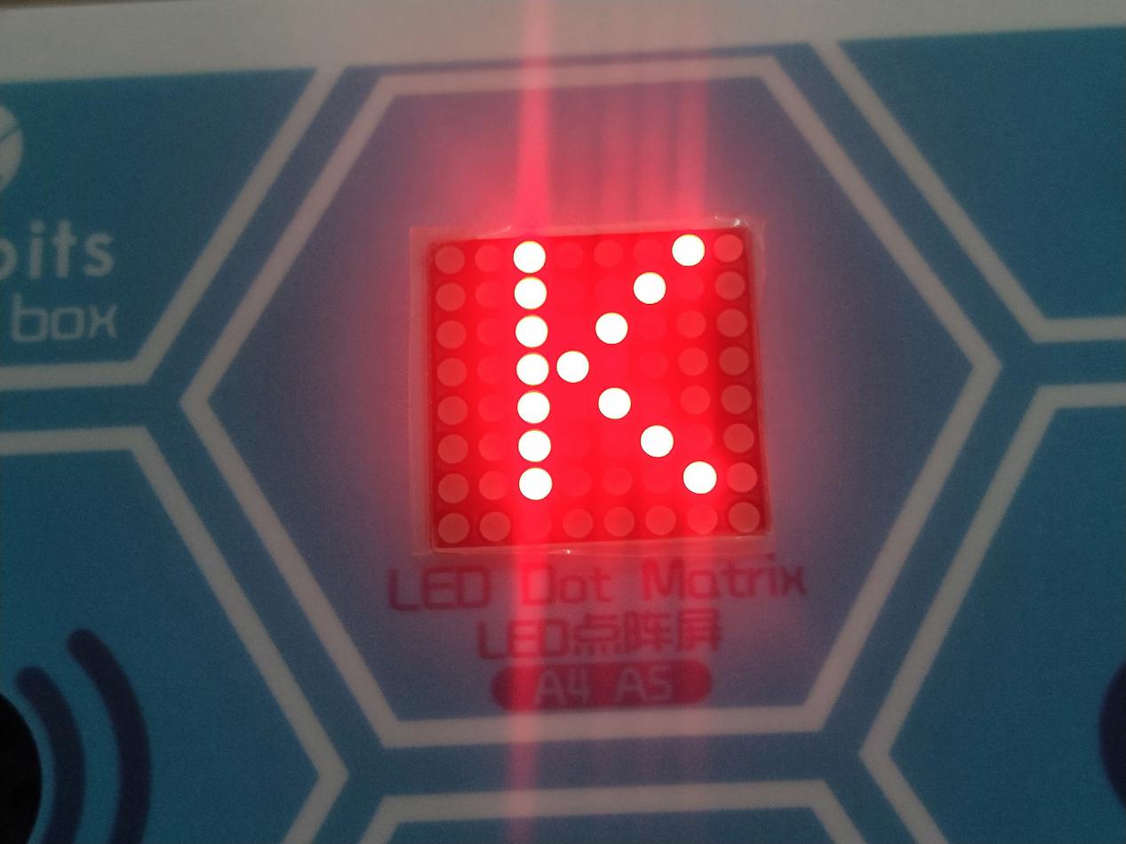
This project is also relatively simple. To render the matrix to display numbers or characters we need to decide a starting point. For example, in the figure below, the blue point spot(2,0) is the starting point of the letter K.
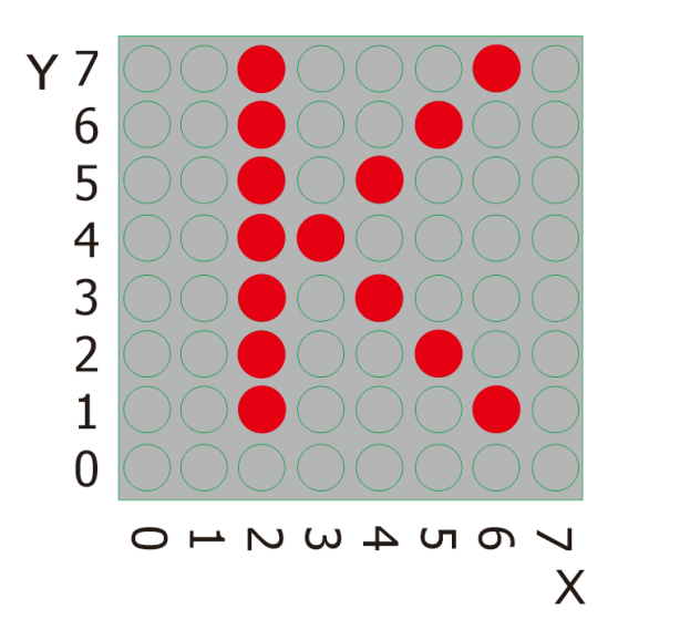
Then we also need to input the position value(2,0) to the code so as to display the letter K.
Project Code
  \*Kidsbits Coding Box

  Project 21

  88 dot matrix-display text and numbers

  http//www.kidsbits.cc

  */

  \#include <ks_Matrix.h\>

  Matrix myMatrix(A4,A5);

  void setup() {

  myMatrix.begin(112);

  myMatrix.clear();

  }

  void loop() {

  myMatrix.setTextSize(1);//Set the size of characters

  myMatrix.setTextWrap(false); // we dont want text to wrap
  so it scrolls nicely

  myMatrix.setTextColor(1);

  myMatrix.setRotation(0);// Rotation

  myMatrix.clear();

  myMatrix.setCursor(2,0);//Input the value of the position

  myMatrix.print("K"); //Input characters or letters

  myMatrix.writeDisplay();

  delay(1000);

  }
next project*
Project 22 Display Images
Project Introduction
Mobile phones, computer screens, billboards and other display devices all consist of many small luminous units. However, the 88 dot matrix has only 64 luminous units. Though it can’t display some nice images with high-resolution, it can show some cute pictures, such as patterns shaped in little heart, cute facial expressions, avatars and others.
Project Principle
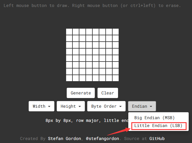
To this end, we will need the help of an online version of dot matrix modulus tool:http://dotmatrixtool.com
Please open the link to enter the following page.
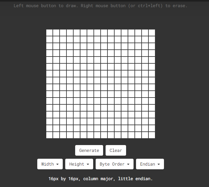
Firstly, as the dot matrix is 88 in this project, please set the height to 8, width to 8, as shown below.
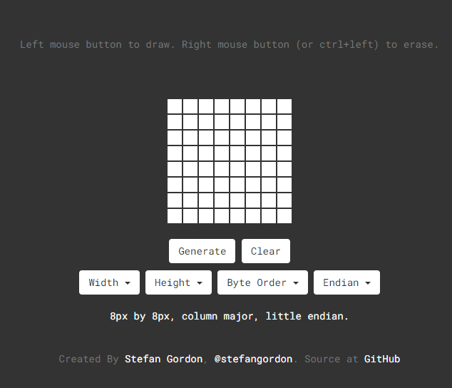
Secondly, Click the Byte order and then choose Row Major as shown below.
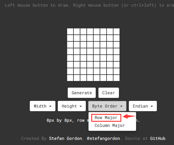
And click the Endian and choose Little Endian(lsb) as shown below;
Thirdly, draw the pattern wanted.

Lastly, click Generate, to yield the hexadecimal data needed.
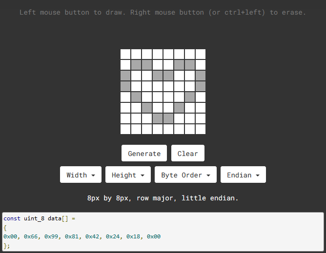
0x00, 0x66, 0x99, 0x81, 0x42, 0x24, 0x18, 0x00
And then integrate the above hexadecimal data into the code
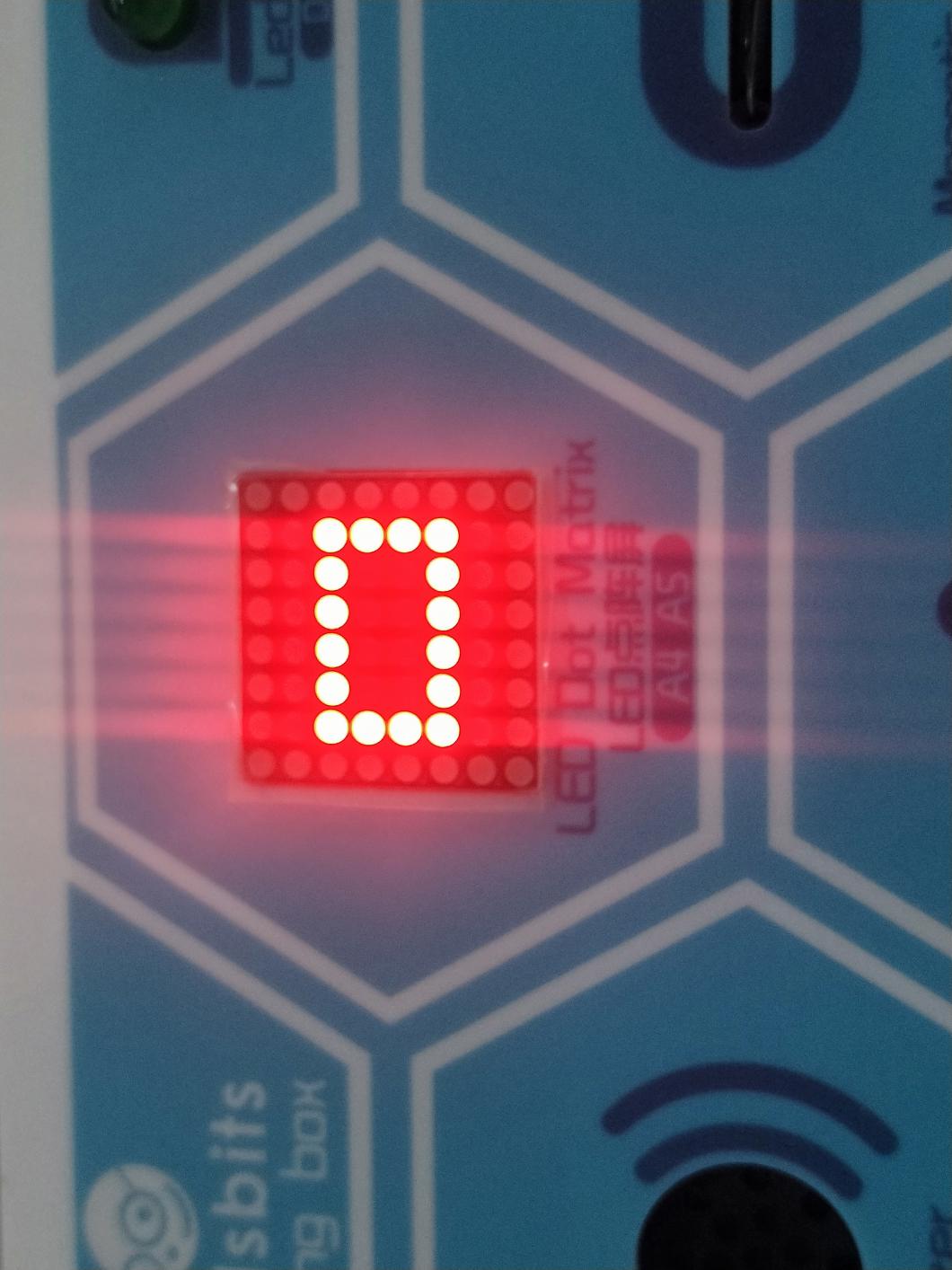
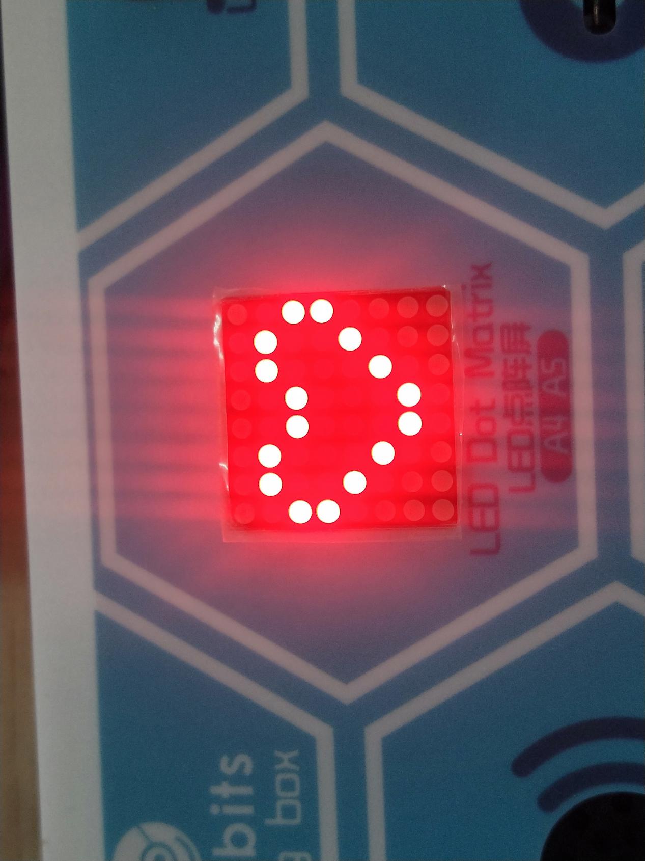
Project Result
Upload the code to the coding box successfully, the LED dot matrix will display as shown in the figure below.
Project Code
  \*Kidsbits Coding Box

  Project 22

  88 dot matrix-display images

  http//www.kidsbits.cc

  */

  \#include <ks_Matrix.h\>

  Matrix myMatrix(A4,A5);

  uint8_t LedArray1[8]={0x00, 0x66, 0x99, 0x81, 0x42, 0x24, 0x18, 0x00};

  uint8_t LEDArray[8];

  void setup(){

  myMatrix.begin(0x70);

  }

  void loop(){

  myMatrix.clear();

  for(int i=0; i\<8; i++)

  {

  LEDArray[i]=LedArray1[7-i];

  for(int j=7; j\>=0; j--)

  {

  if((LEDArray[i]&0x01)\>0)

  myMatrix.drawPixel(j, i,1);

  LEDArray[i] = LEDArray[i]\>\>1;

  }

  }

  myMatrix.writeDisplay();

  }
Project Result
Upload the code to the coding box successfully, the LED dot matrix will display as shown in the figure below.
next project***
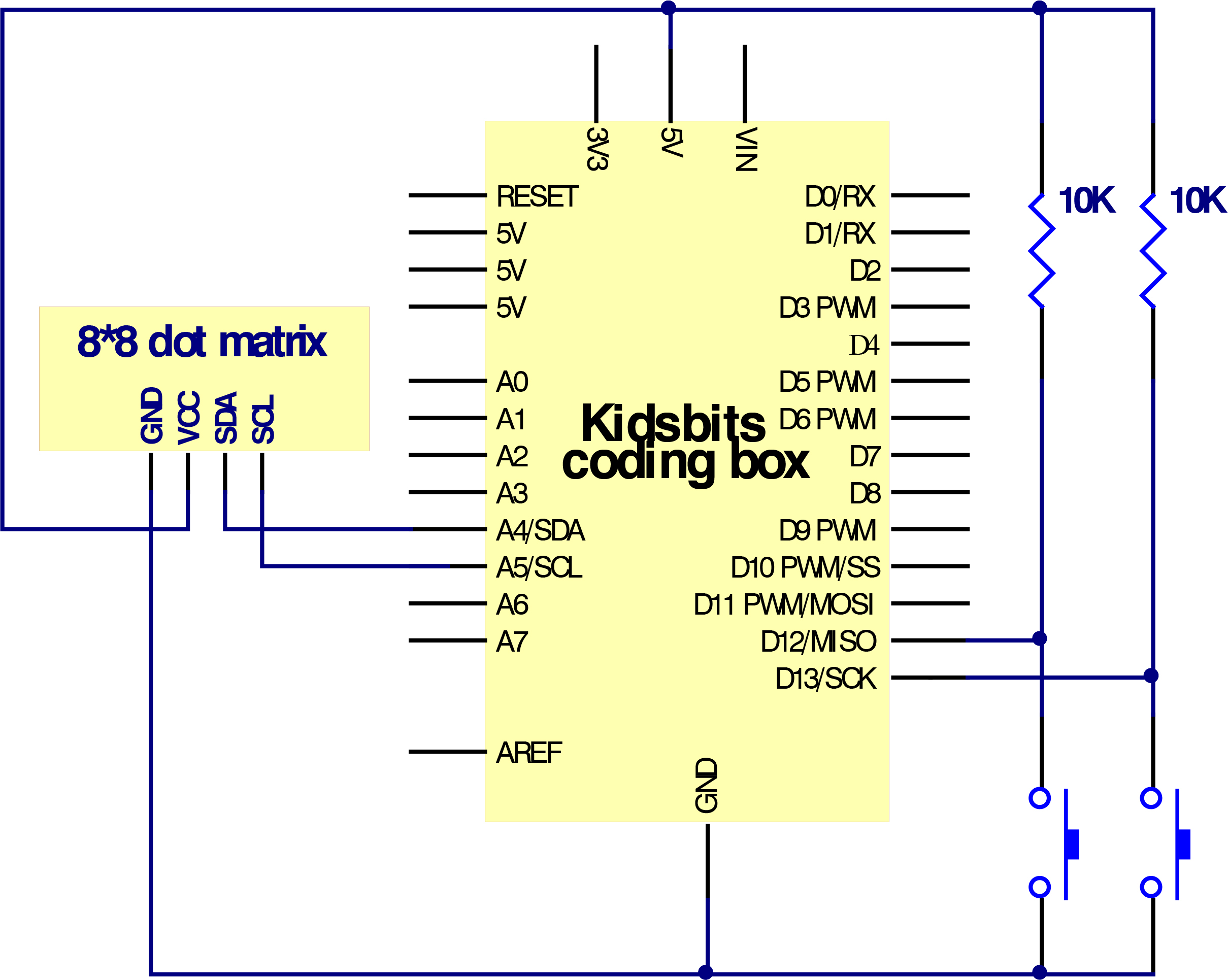
Project 23 Buttons+88 Dot Matrix
Project Introduction
There are two built-in buttons on the MAX board, which we have used to control DIY lamps in previous project. While in this project, we will combine these buttons with the 88 dot matrix to make displays.
Working Principle
Preciously,we learned that the signal pins of the two buttons should be connected with D2 and D3 and how to make the matrix to show characters. Bearing these knowledge in mind, we will complete this project. When the button on the left side is pressed, the letter L will be displayed while when the right is pressed, R will be shown.
Project Circuit
Project Code
  \*Kidsbits Coding Box

  Project 23

  88 dot matrix-knob control

  http//www.kidsbits.cc

  */

  \#include <ks_Matrix.h\>

  Matrix myMatrix(A4,A5);

  int K1=12;

  int K2=13;

  int x;

  void setup()

  {

  myMatrix.begin(112);

  myMatrix.clear();

  pinMode(K1,INPUT);

  pinMode(K2,INPUT);

  myMatrix.drawCircle(3,3, 2, 1);

  myMatrix.writeDisplay(); // write the changes we just made to the display

  }

  void loop()

  {

  int K1_level=digitalRead(K1);

  int K2_level=digitalRead(K2);

  if(K1_level==0)

  {

  myMatrix.setTextSize(1);

  myMatrix.setTextWrap(false); // we dont want text to wrap
  so it scrolls nicely

  myMatrix.setTextColor(1);

  myMatrix.setRotation(0);

  myMatrix.clear();

  myMatrix.setCursor(2,0);

  myMatrix.print("L");

  myMatrix.writeDisplay();

  }

  if(K2_level==0)

  {

  myMatrix.setTextSize(1);

  myMatrix.setTextWrap(false); // we dont want text to wrap
  so it scrolls nicely

  myMatrix.setTextColor(1);

  myMatrix.setRotation(0);

  myMatrix.clear();

  myMatrix.setCursor(2,0);

  myMatrix.print("R");

  myMatrix.writeDisplay();

  }}
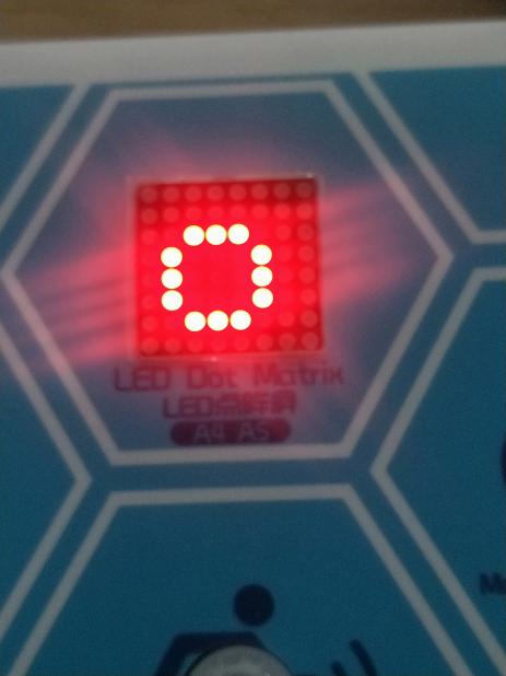
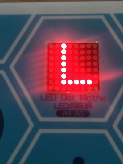
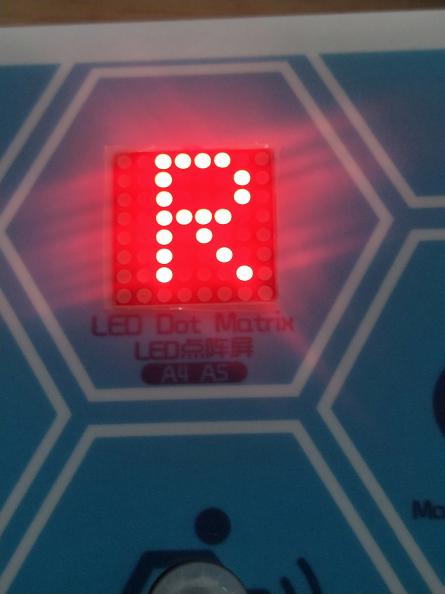
Project Result
A successful uploading of the code to the coding box, the LED dot matrix first displays a circle; Press the left button and the LED dot matrix displays the letter “L”;Press the right button and the LED dot matrix displays the letter “R”.
|  |
|
 |
|
 |
|———|————–|—————–|
|
|———|————–|—————–|
next project*
Project 24 Light Sensor+88 Dot Matrix
Project Introduction
We have made a night light based on the property of the light sensor that its resistance decreases with the increasing of the light. In this project, we will show you something intriguing too. We will combine the matrix with the light sensor to display the length of the light.
Project Principle
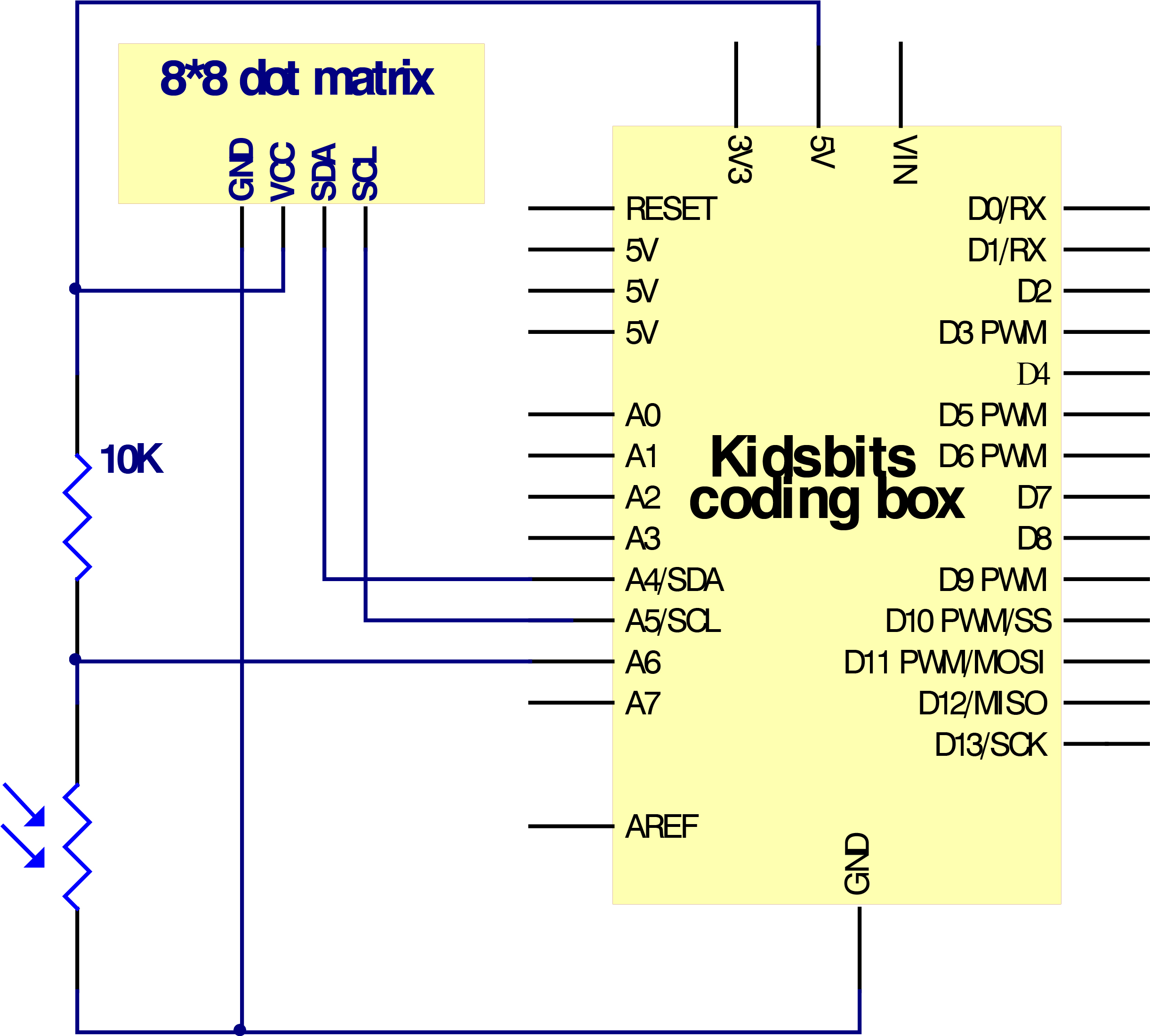
The signal pin of the light sensor is wired with the A6 of the MAX development board. And the light column displayed on the 88 dot matrix will change with the external light detected by the light sensor. When the detected light is darker, the light column displayed is shorter; when the light becomes brighter, the light column gets longer;
Project Circuit
Project Code
  \*Kidsbits Coding Box

  Project 24

  88 dot matrix-light control

  http//www.kidsbits.cc

  */

  \#include <ks_Matrix.h\>

  Matrix myMatrix(A4,A5);

  int light = A6;

  int Light_val;

  void setup() {

  pinMode(A6,INPUT);

  myMatrix.begin(112);

  myMatrix.clear();

  }

  void loop() {

  Light_val=analogRead(A6);

  Light_val=map(Light_val,0,1023,0,15);

  myMatrix.clear();

  myMatrix.drawLine(3,0, 3,Light_val, 1);

  myMatrix.writeDisplay(); // write the changes we just made to the display

  delay(10);

  }
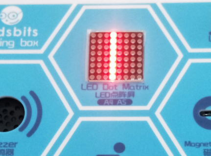
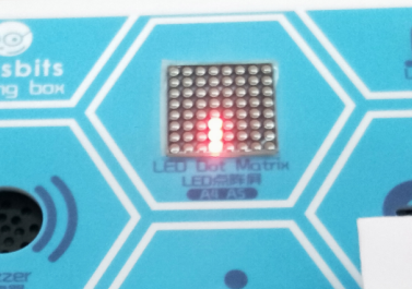
Project Result
After uploading the code to the coding box, the LED dot matrix displays a line when the sensor detect light. And when the light sensor is blocked, the height of the dot matrix decreases.The stronger the light detected by the light sensor, the higher the height of the dot matrix displays.
next project***
Project 25 Sound Sensor+88 Dot Matrix
Project Introduction
Previously, we used a sound sensor and LED to make a voice-controlled lamp. Here we will use the sound sensor and the 88 dot matrix to interact together and do some interesting projects.
Working Principle
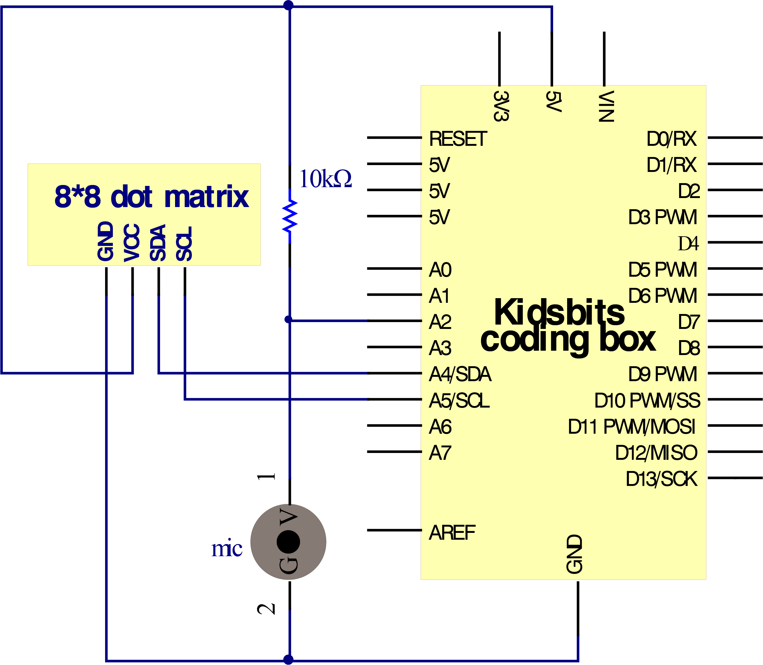
The signal pin of the sound sensor is connected with the A2 on the MAX development board. And the cycle displayed on the matrix can get bigger as the sound sensed increases.
Project Circuit
Project Code
  \*Kidsbits Coding Box

  Project 25

  88 dot matrix-sound control

  http//www.kidsbits.cc

  */

  \#include \<ks_Matrix.h\>

  Matrix myMatrix(A4,A5);

  int mic = A2;

  int Mic_val;

  void setup() {

  pinMode(mic,INPUT);

  myMatrix.begin(112);

  myMatrix.clear();

  }

  void loop() {

  Mic_val=analogRead(mic);

  Mic_val=map(Mic_val,0,1023,0,10);

  myMatrix.clear();

  myMatrix.drawCircle(3,3,Mic_val, 1);

  myMatrix.writeDisplay(); // write the changes we just made to the display

  delay(10);

  }
Project Result
After uploading the code to the coding box, we find that the LED dot matrix displays a dot when the sound sensor detects a sound. When the sound is loud enough, the LED dot matrix displays a circle with a dot as the center. The louder the sound, the larger the circle.